Systems and program product for heat exchanger network energy efficiency assessment and lifetime retrofit

a heat exchanger and energy efficiency assessment technology, applied in the field of energy recovery systems, can solve the problems of incompletely different network structure retrofit solutions, package rejection, and inability to achieve the best, and achieve the effect of eliminating lost topology energy

Active Publication Date: 2011-07-21
SAUDI ARABIAN OIL CO
View PDF19 Cites 19 Cited by
  • Summary
  • Abstract
  • Description
  • Claims
  • Application Information

AI Technical Summary

Benefits of technology

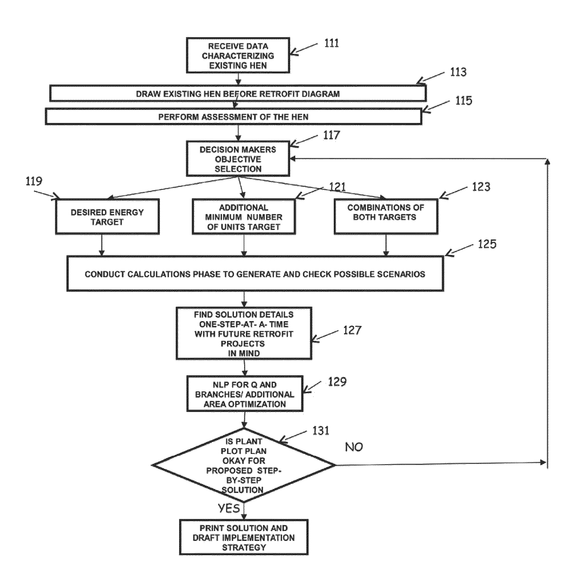
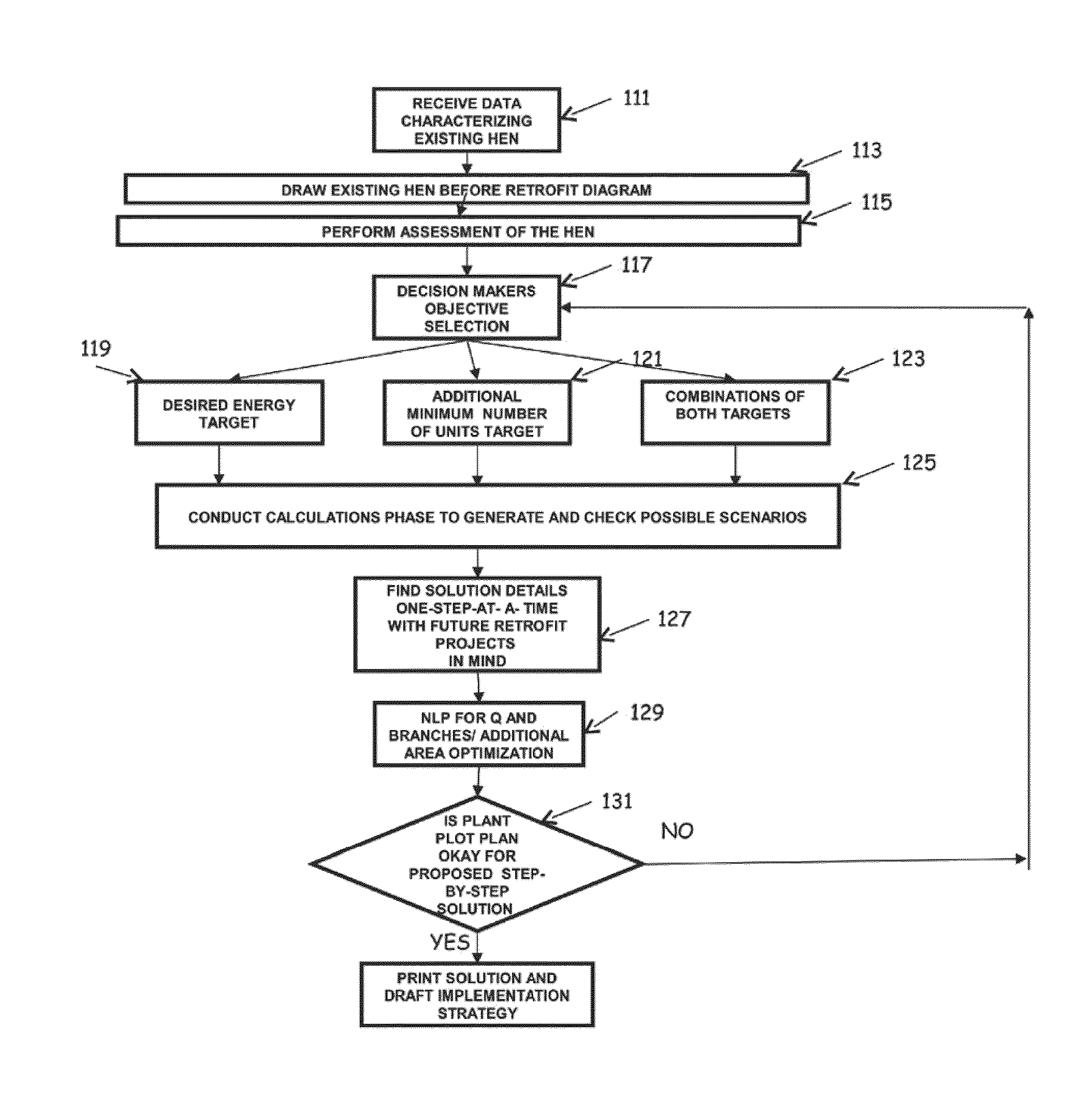
[0046]Various steps can also include graphically displaying the current and proposed heat transfer structures according to a new and unique graphical methodology. The steps can also include selecting an optimal pinch point location from an energy point of view, minimum number of units to be added point of view, or both, and calculating the minimum number of HE units. The steps that also include employing a marching technique to discover/calculate rigorous new retrofit targets upon {ΔT_min_i} systematic reduction and/or process condition changes, marking cross the pinch and utility violators, discovering and correcting wrong matching via creating new utilities path(s) to include eliminating lost-in-topology energy due to using less than the minimum number of HE units and due to wrong matching.
[0047]Various embodiments of the present invention advantageously exhibit several folds of uniqueness, such as, for example, in the methodology of representing the existing HEN, in the methodology of testing and analyzing the existing HEN from “energy-efficiency” point of view, in the energy consumption and number of units targeting phase, and finally in the systematic finding of the retrofit solutions, which is evolutionary in implementation but revolutionary in thinking as it serves the novel concept of plant lifetime retrofit-ability without contradictio

Problems solved by technology

Using a different starting point, however, will likely result in a completely different network structure retrofit solution.
As such, if one starts with the wrong ΔT_min, the wrong structure will be obtained, and evolutionary heuristics and optimization techniques (NLP) will not lead to the best results since radical moves/changes from one structure to another are not feasible or possible.
That is, if the designer cannot accept the entire solution structure for one reason or another (e.g., capital needed and/or time for implementation, affect on other process units, etc.) the package will have to be rejected.
This can be troublesome as the targets defined for area and investment costs are not rigorous and very crude.
The use of pinch technology rules to find topological modifications in the existing HENs to overcome the so called network pinch, however, is not rigorous since it is based upon the assumption that the network pinch and the process pinch are not going to change its location due to the taken topological modification.
As the assumption is not correct, topological modifications can have counter effects on each other to the extent that they may completely negate the possibility of doing future retrofit projects.
That is, it may become impossible to employ a certain retrofit project due its counter effect on the previous projects, and so on, making the retrofit projects in sustainable.
For example, if the current HEN retrofit process is conducted using pinch technology concept including the evolutionary network pinch method, and then if in at least one time at any future network retrofit process a different pinch point location arises, e.g., due to process parametric and/or structural modifications, and if the different pinch point location indicates a need for a lesser minimum number of units than the one used in previous HEN retrofit project, the result may be a wasting of some of the HE units already added in the previous HEN retrofit.
Such use, however, is crude, based upon heuristics, and is not rigorous (repeatably accurate).
Although, as noted previously, most commercial software are currently using mathematical programming techniques to complement other methodologies, pure mathematical programming techniques have been less well received, particularly in the industry community.
For example, in the most widely used pinch tech

Method used


Image

  • Systems and program product for heat exchanger network energy efficiency assessment and lifetime retrofit
  • Systems and program product for heat exchanger network energy efficiency assessment and lifetime retrofit
  • Systems and program product for heat exchanger network energy efficiency assessment and lifetime retrofit

Examples


Embodiment Construction

[0085]The present invention will now be described more fully hereinafter with reference to the accompanying drawings, which illustrate embodiments of the invention. This invention may, however, be embodied in many different forms and should not be construed as limited to the illustrated embodiments set forth herein. Rather, these embodiments are provided so that this disclosure will be thorough and complete, and will fully convey the scope of the invention to those skilled in the art. Like numbers refer to like elements throughout. Prime notation, if used, indicates similar elements in alternative embodiments.

[0086]Many different types of processes consume multiple steam levels and electricity to obtain an output result, or to produce a required product or compound. With large scale processes which consume significant amounts of steam for instance, it is preferable to optimize the steam and power system where possible. Heat exchanger network retrofit for waste energy recovery under ...


PUM


Abstract

Systems and program product for managing/assessing heat exchanger network energy efficiency and retrofit for an industrial facility, are provided. An embodiment of a system can include a heat exchanger network analysis and design computer and heat exchange network analysis and design program product configured to cause the heat exchange network analysis and design computer to perform various operations including those for determining an optimal heat exchanger network retrofit projects sequence extending between a current heat exchanger network retrofit project satisfying a current desired waste energy recovery goal and a future heat exchanger network retrofit project satisfying the final waste energy recovery goal. The heat exchanger network retrofit projects sequence can be configured so that each subsequent project within the heat exchanger network retrofit projects sequence does not contradict any of the previous projects within the heat exchanger network retrofit projects sequence.

Description

RELATED APPLICATIONS[0001]This patent application is a continuation-in-part of U.S. patent application Ser. No. 12 / 898,475, filed Oct. 5, 2010, titled “Systems, Program Product, and Methods For Synthesizing Heat Exchanger Networks That Account For Future Higher Levels of Disturbances and Uncertainty and Identifying Optimal Topology For Future Retrofit,” which claims priority to the benefit of U.S. Provisional Patent Application No. 61 / 356,900, filed Jun. 21, 2010, titled “Systematic Synthesis Method and Program Product For Heat Exchanger Network Life-Cycle Switchability and Flexibility Under All Possible Combinations of Process Variations” and U.S. Provisional Application No. 61 / 256,754, filed Oct. 30, 2009, titled “System, Method, and Program Product for Synthesizing Non-Constrained and Constrained Heat Exchanger Networks and Identifying Optimal Topoloy for Future Retrofit,” and which is a continuation-in-part of U.S. patent application Ser. No. 12 / 715,255, filed Mar. 1, 2010, titl...

Claims


Application Information

Patent Timeline
IPC IPC(8): G06Q10/00
CPCF01K13/02G05B13/021G06F17/5009G06Q10/06313G05B15/02G06F30/20Y02P80/10
Inventor NOURELDIN, MAHMOUD BAHY
Owner SAUDI ARABIAN OIL CO
Why Eureka
Try Eureka