Waste Heat Recovery System of Internal Combustion Engine

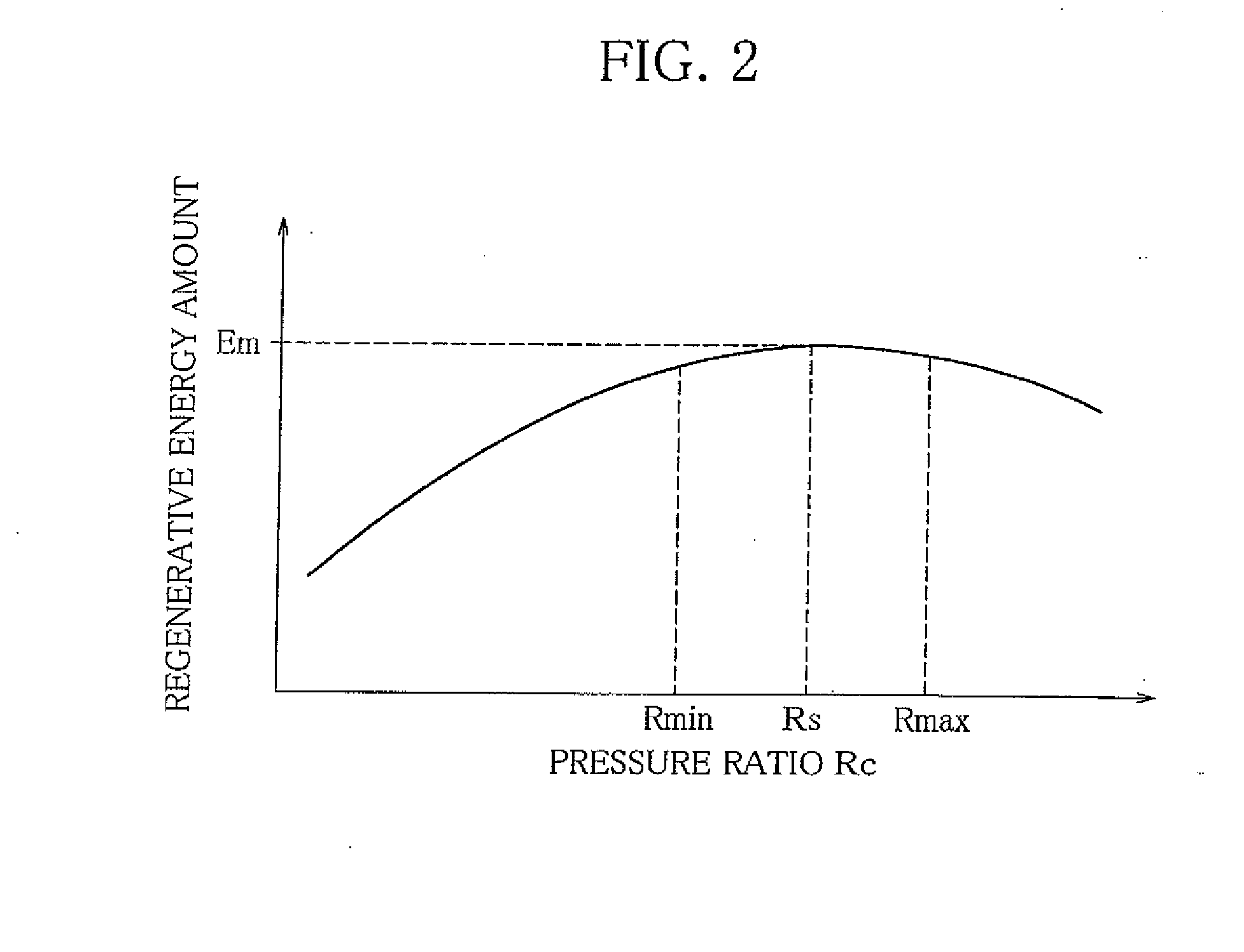
a heat recovery system and internal combustion engine technology, applied in the direction of machines/engines, mechanical equipment, lighting and heating apparatus, etc., can solve the problems of reducing the output of the expander shaft, namely, regenerative energy amount, and the amount of evaporation of the heat-transfer media is not sufficient, so as to prevent a decrease in and increase the pressure of the heat-transfer media

Inactive Publication Date: 2011-08-11
SANDEN CORP
View PDF14 Cites 60 Cited by
  • Summary
  • Abstract
  • Description
  • Claims
  • Application Information

AI Technical Summary

Benefits of technology

[0032]According to the waste heat recovery system of an internal combustion engine claimed in claim 1 of the invention, when the determination means determines that it is necessary to increase the pressure of the heat-transfer media in the heat exchanger, the controller increases the pressure of the heat-transfer media in the heat exchanger by using the flow-rate regulating valve. This prevents a decrease in pressure of the heat-transfer media at the expander inlet, and thus prevents a decrease in output of the expander, or a reduction in regenerative energy amount.
[0033]According to the waste heat recovery system of an internal combustion engine claimed in claim 2, the determination means makes a proper determination by using preset pressure as a criterion for determination.
[0034]According to the waste heat recovery system of an internal combustion engine claimed in claim 3, since the determination means uses the preset pressure ratio as a criterion, it is properly determined whether or not the pressure of the heat-transfer media in the heat exchanger needs to be increased.
[0035]According to the waste heat recovery system of an internal combustion engine claimed in claim 4, the determination means makes a determination only if the rotational velocity of the rotary shaft of the expander is equal to or higher than the preset rotational velocity, and the regenerative energy amount is reliably prevented from being reduced by the increase of the rotational velocity.
[0036]According to the waste heat recovery system of an internal combustion engine claimed in claim 5, the frequency of the flow rate regulation by the flow-rate regulating valve is reduced due to the tank. The flow rate regulation induces a temporary decrease in output of the expander, causing a disturbance to control on the speed of the internal combustion engine. The control on the internal combustion engine speed is stabilized by reducing the frequency of the flow rate regulation. In the case of a vehicle, the stable engine speed control makes a driver feel comfortable driving the vehicle. In addition, the reduction of frequency of the flow rate regulation contributes to prolongation of life of the flow-rate regulating valve.
[0037]According to the waste heat recovery system of an internal combustion engine claimed in claim 6, the heat-transfer media are increased in enthalpy by being heated within the tank. As a result, when the regulation by the flow-rate regulating valve is eliminated, the expander output is further amplified.

Problems solved by technology

There is a limit to the amount of heat that can be absorbed by heat-transfer media within a heat exchanger, or an evaporator.
The amount of evaporation of the heat-transfer media is therefore not sufficiently increased even if the rotational velocity of the expander shaft is increased.
Consequently, the pressure of the heat-transfer media at the inlet of the expander is reduced, and this results in a decrease in output from the expander shaft, namely, regenerative energy amount.

Method used


Image

  • Waste Heat Recovery System of Internal Combustion Engine
  • Waste Heat Recovery System of Internal Combustion Engine
  • Waste Heat Recovery System of Internal Combustion Engine

Examples


embodiment 1

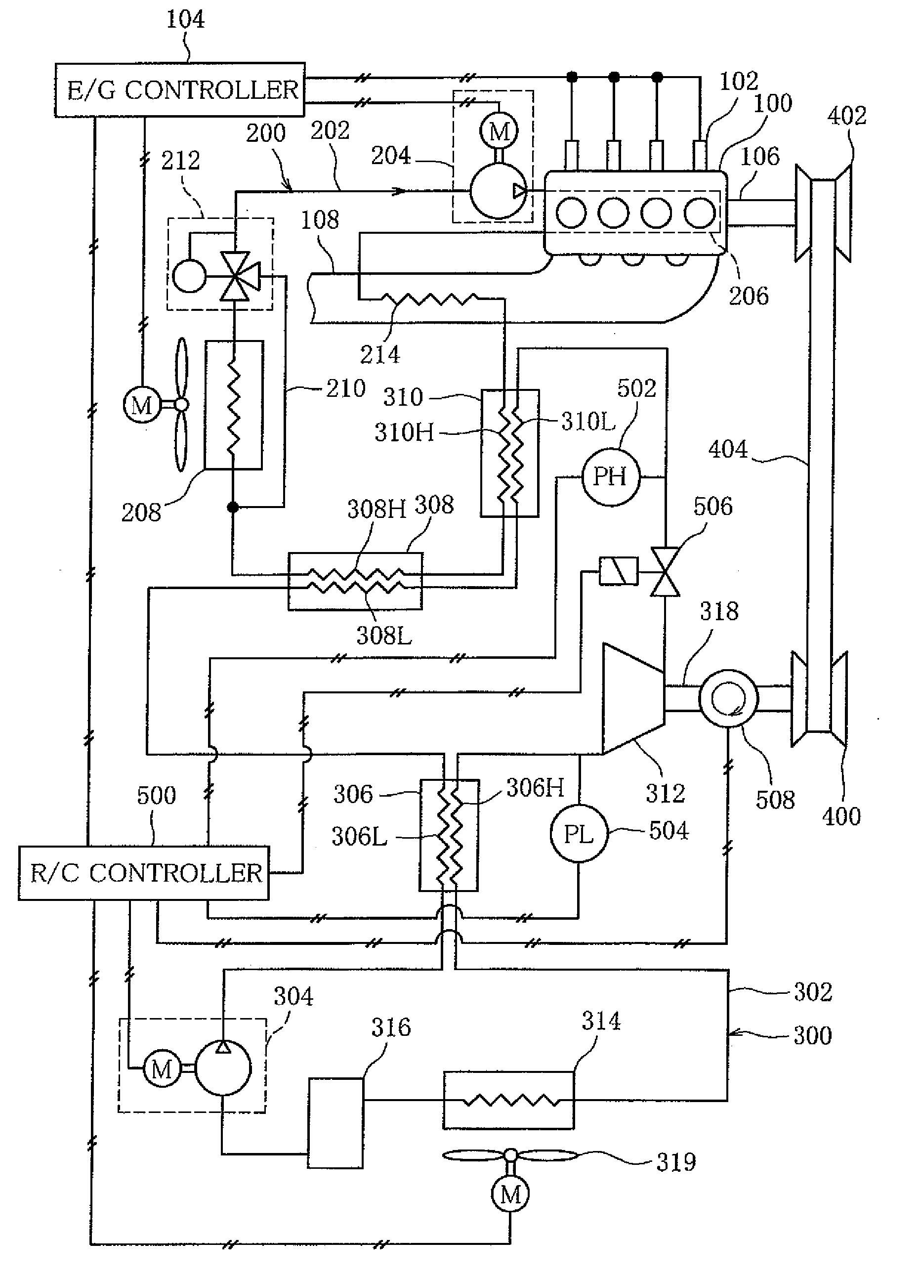
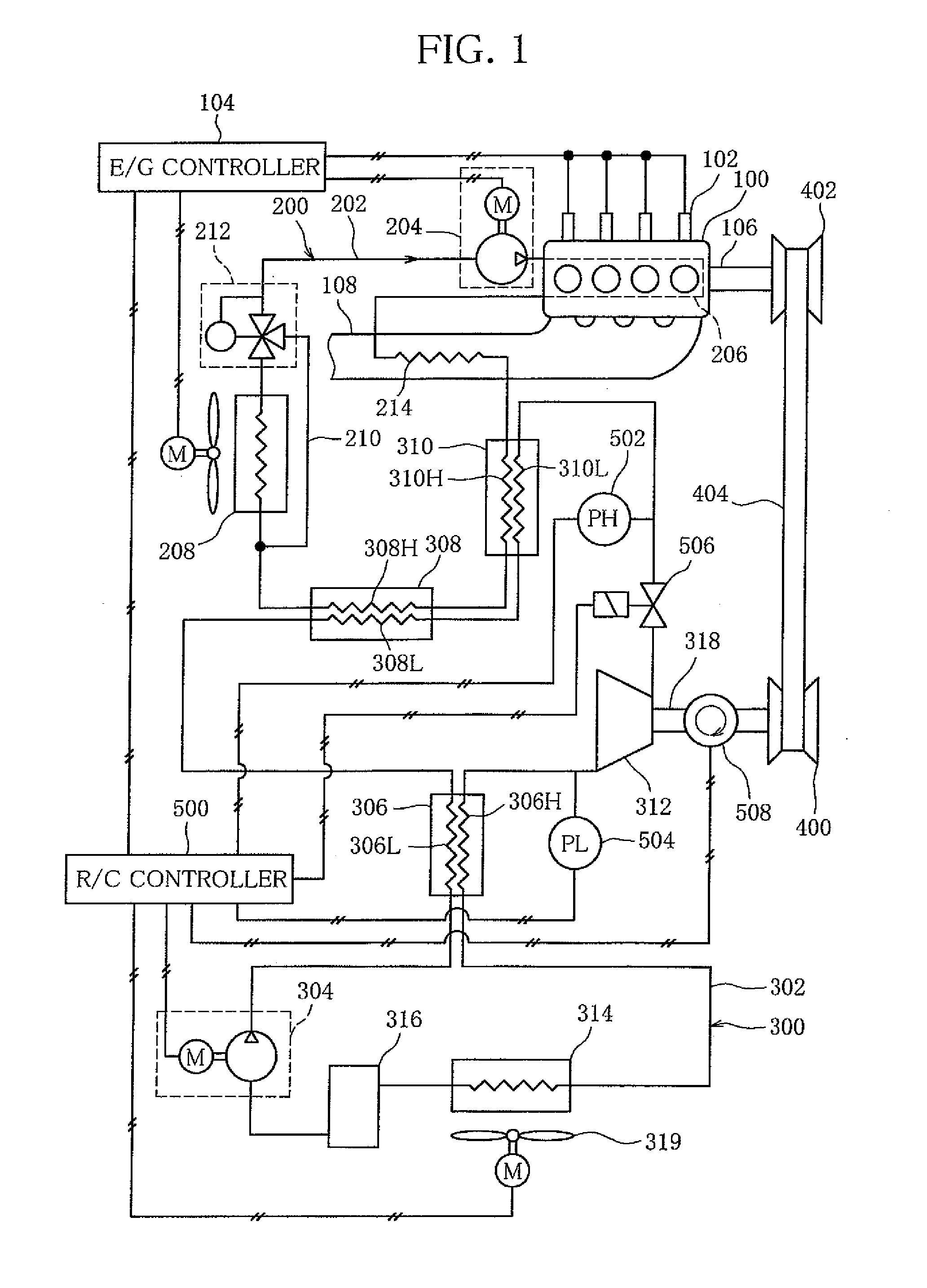
[0074]FIG. 1 shows a schematic configuration of a waste heat recovery system of an internal combustion engine 100 according to one embodiment of the invention.

[0075]The waste heat recovery system of the internal combustion engine 100 is designed to convert into energy (regenerative energy) the heat generated in the internal combustion engine 100. More specifically, the heat generated in the internal combustion engine 100 is supplied through a cooling device 200 of the internal combustion engine 100 to a Rankine cycle circuit 300. The heat is then converted into torque in the Rankine cycle circuit 300. The torque is transmitted to the internal combustion engine 100 and aids the internal combustion engine 100.

[0076]The internal combustion engine 100 is, for example, a diesel engine for a vehicle. Diesel oil as fuel is supplied into cylinders of the internal combustion engine 100 through injectors 102. The injectors 102 are controlled by an E / G controller 104. An applied amount of an a...


PUM


Abstract

A waste heat recovery system of an internal combustion engine, in which the amount of regenerative energy transmitted to the internal combustion engine is increased with a simple mechanism. A controller of the waste heat recovery system of an internal combustion engine has at least determination means that makes a determination as to whether it is necessary to increase the pressure of heat-transfer media in a heat exchanger, on the basis of the pressure detected by the high-pressure sensor. When the determination means determines that it is necessary to increase the pressure in the heat exchanger, the controller causes a flow-rate regulating valve (506) to start regulating the flow rate of the heat-transfer media while leaving the pump working. The controller causes the flow-rate regulating valve to continue the regulation at least until the determination means determines that it is not necessary to increase the pressure in the heat exchanger, and then terminates the regulation.

Description

TECHNICAL FIELD [0001]The present invention relates to a waste heat recovery system of an internal combustion engine, and more specifically to a waste heat recovery system of an internal combustion engine, which is suitable to a vehicle.BACKGROUND ART [0002]A waste heat recovery system of an internal combustion engine has a Rankine cycle circuit. The Rankine cycle circuit includes a circulation path through which heat-transfer media are circulated. A pump, a heat exchanger, an expander and a condenser are interposed in the circulation path in the order named. In the heat exchanger, the heat-transfer media are heated by using the heat released from the internal combustion engine, and the heat-transfer media that have been heated are expanded within the expander. In this process, power is supplied through the rotary shaft of the expander, and is used as regenerative energy.[0003]As to the heat engine disclosed in Patent Document 1, for example, the engine is aided by regenerative ener...

Claims


Application Information

Patent Timeline
Patent Type & Authority Applications(United States)
IPC IPC(8): F02G5/02
CPCF01K13/02F01K23/065F01K23/14F01K25/10Y02T10/166F01N2240/02F02G5/02Y02T10/16F01N5/02Y02T10/12
Inventor KASUYA, JUNICHIRO
Owner SANDEN CORP
Why Eureka
Try Eureka