Composite cutter substrate to mitigate residual stress

a technology of residual stress and substrate, which is applied in the field of composite cutting structures, can solve the problems of permanent damage and structural failure of pcd, delamination between the diamond layer and the substrate, and deterioration of pcd

Inactive Publication Date: 2011-08-11
SMITH INT INC
View PDF29 Cites 32 Cited by
  • Summary
  • Abstract
  • Description
  • Claims
  • Application Information

AI Technical Summary

Benefits of technology

[0020]In one aspect, embodiments disclosed herein relate to a method of forming a cutting element, which includes filling at least one non-planar region on an upper surface of a carbide substrate with a diamond mixture comprising diamond particles, subjecting the substrate and the diamond mixture to high pressure high temperature sintering conditions to form a reduced-CTE substrate having polycrystalline diamond that extends a depth into the reduced-CTE substrate in an interface region, and an upper surface that comprises a composite surface of diamond and carbide, and attaching a polycrystalline diamond body to the composite surface of the reduced-CTE substrate.

Problems solved by technology

Conventional PCD is stable at temperatures of up to 700-750° C., after which observed increases in temperature may result in permanent damage to and structural failure of PCD.
In particular, heat caused by friction between the PCD and the work material causes thermal damage to the PCD in the form of cracks, which lead to spalling of the diamond layer and delamination between the diamond layer and substrate.
This deterioration in PCD is due to the significant difference in the coefficient of thermal expansion of the binder material, which is typically cobalt, as compared to diamond.
Upon heating of PCD, the cobalt and the diamond lattice will expand at different rates, which may cause cracks to form in the diamond lattice structure and result in deterioration of the PCD.
High operating temperatures may also lead to back conversion of the diamond to graphite causing loss of microstructural integrity, strength loss, and rapid abrasive wear.
However, some of the problems described above that plague PCD cutting elements, i.e., chipping, spalling, partial fracturing, cracking or exfoliation of the cutting table, are also often encountered in TSP cutters or other types of cutters having an ultra hard diamond-like cutting table such as polycrystalline cubic boron nitride (PCBN) bonded on a cemented carbide substrate.
In particular, it has been observed that TSP cutters are slightly more prone to spalling and delamination under severe loads.
These problems result in the early failure of the cutting table and thus, in a shorter operating life for the cutter.
These problems, i.e., chipping, spalling, partial fracturing, cracking, and exfoliation of the PDC diamond layer may be caused in part by the difference in the coefficient of thermal expansion between the diamond and the substrate.
Further, different contractions between the diamond layer and carbide substrate generate stresses in both bodies.
These stresses may induce larger stresses, which may ultimately lead to material failure, because diamond and substrate materials typically have a high modulus (i.e., stiffness).
Additionally, the formation of a non-planar interface becomes more difficult to achieve when sintering a preformed diamond layer to a carbide substrate because any imprecision between mating non-planar surfaces of the diamond and substrate may cause cracking in the diamond layer.

Method used


Image

  • Composite cutter substrate to mitigate residual stress
  • Composite cutter substrate to mitigate residual stress
  • Composite cutter substrate to mitigate residual stress

Examples


examples

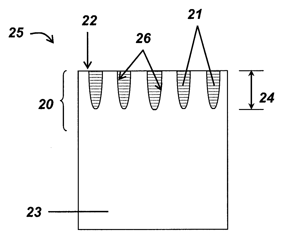
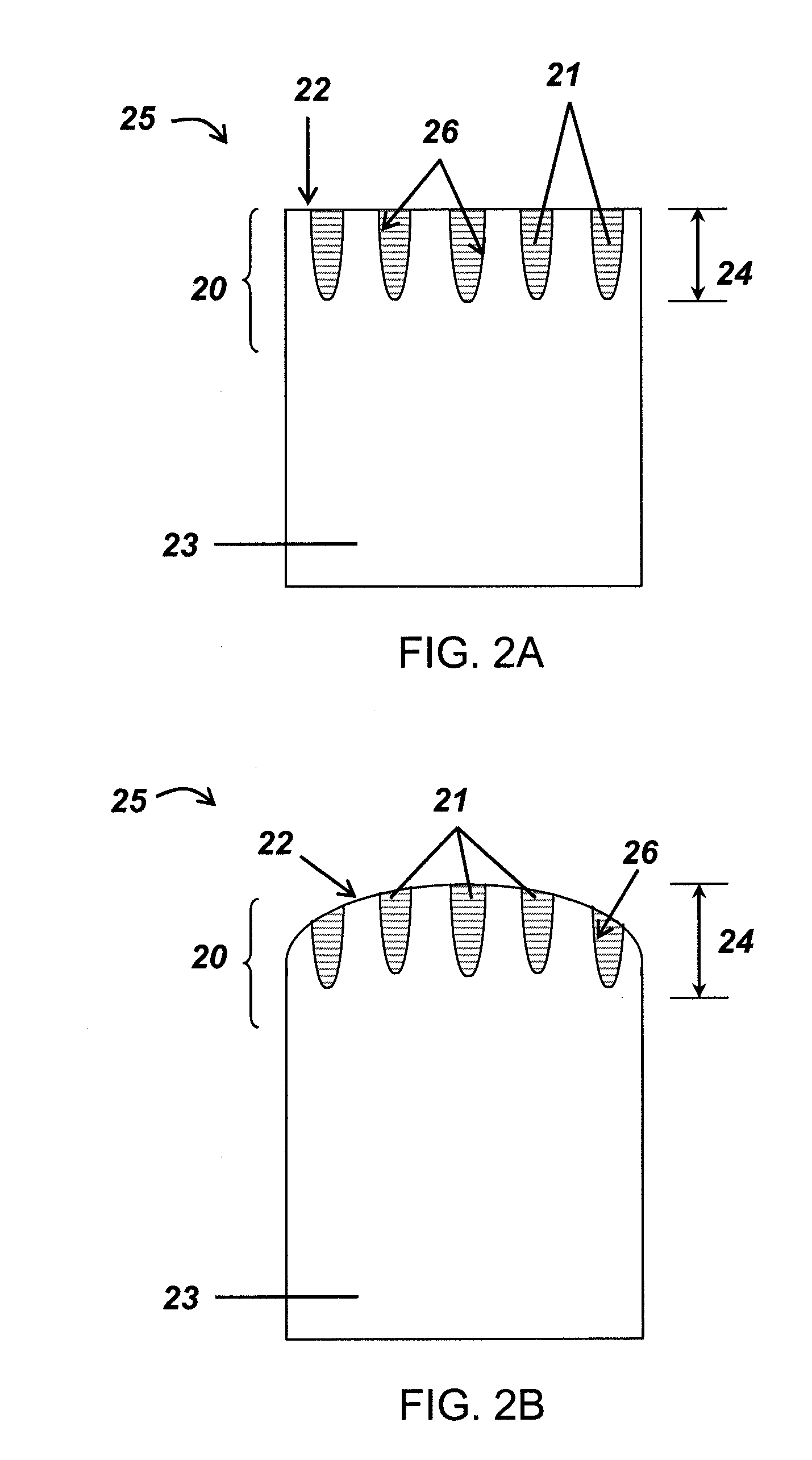
[0088]In an exemplary embodiment, as shown in FIGS. 6A-C, non-planar regions are formed in the upper surface of a carbide substrate 63 (along the outer diameter of the substrate in this embodiment). An excess amount of a mixture of diamond particles and optional catalyst material 61 (61a being the diamond particles that “fill” the non-planar geometry of the substrate 63 and 61b being the “excess” diamond particles) may be placed adjacent to the non-planar upper surface such that the mixture 61b extends a distance above the carbide substrate upper surface. The mixture 61 and the substrate 63 are then subjected to a HPHT sintering process, whereby PCD-filled regions 66 and a PCD layer (from excess mixture 61b) are formed. The PCD layer is then removed, leaving a reduced-CTE substrate 60. The removed PCD layer is then leached to form a TSP diamond layer 64, and reattached to the reduced-CTE substrate 60 by HPHT sintering.

[0089]Alternatively, a lesser amount of diamond particles 61a may...


PUM

PropertyMeasurementUnit
temperatureaaaaaaaaaa
depthaaaaaaaaaa
depthaaaaaaaaaa

Abstract

A method of forming a cutting element that includes filling at least one non-planar region on an upper surface of a carbide substrate with a diamond mixture, subjecting the substrate and the diamond mixture to high pressure high temperature sintering conditions to form a reduced-CTE substrate having polycrystalline diamond that extends a depth into the reduced-CTE substrate in an interface region, and an upper surface made of a composite surface of diamond and carbide, and attaching a polycrystalline diamond body to the composite surface of the reduced-CTE substrate is disclosed.

Description

CROSS-REFERENCE TO RELATED APPLICATIONS[0001]Pursuant to 35 U.S.C. §119(e), this application claims priority to U.S. Provisional Application 61 / 302,701, filed on Feb. 9, 2010, which is herein incorporated by reference in its entirety.BACKGROUND OF INVENTION[0002]1. Field of the Invention[0003]Embodiments disclosed herein relate generally to composite cutting structures.[0004]More particularly, embodiments disclosed herein relate to polycrystalline diamond cutting elements formed to mitigate the residual stresses contained therein.[0005]2. Background Art[0006]Polycrystalline diamond compact (“PDC”) cutters have been used in industrial applications including rock drilling and metal machining for many years. In a typical application, a compact of polycrystalline diamond (“PCD”) (or other superhard material, such as polycrystalline cubic boron nitride) is bonded to a substrate material, which is typically a sintered metal-carbide to form a cutting structure. PCD comprises a polycrystall...

Claims


Application Information

Patent Timeline
Patent Type & Authority Applications(United States)
IPC IPC(8): E21B10/36B24D3/04B01J3/06B24D3/10
CPCB22F2005/001E21B10/5735C22C29/08C22C26/00C23F1/02C23F1/28E21B10/567E21B10/573
Inventor SHEN, YUELINZHANG, YOUHESHI, JIBINBURHAN, YURILOCKWOOD, GREGORY T.
Owner SMITH INT INC
Why Eureka
Try Eureka