Rechargeable metal-air battery

a rechargeable metal-air battery technology, applied in the field of metal-air batteries, can solve the problems of increasing weight, the theoretical upper limit of the battery's energy density, and the limited practical use of the metal-air battery as a non-rechargeable metal-air battery, so as to reduce the increase of contact resistance and improve battery performance and service life.

Inactive Publication Date: 2011-08-11
HITACHI LTD
View PDF7 Cites 34 Cited by
  • Summary
  • Abstract
  • Description
  • Claims
  • Application Information

AI Technical Summary

Benefits of technology

[0044]According to the present invention, it is possible to suppress the increase of contact resistance due to dimensional cha...

Problems solved by technology

However, the theoretical upper limit of the battery's weight energy density is considered to be 400 Wh/kg or so.
Since a transition metal element which is a constituent element of the positive electrode material is heavy metal, assembling the positive electrode material into a storage battery results in an increase in weight.
The metal-air battery is limited to practical use as a non-rechargeable metal-air battery, as typified by a zinc-based metal-air battery which until now has been used as a power supply for hearing aids.
Accordingly, the metal-air battery has not yet been put into practical use as a rechargeable metal-air battery capable of charge and discharge.
The major reasons that the metal-air battery is prevented from being turned into a rechargeable battery inc...

Method used


Image

  • Rechargeable metal-air battery
  • Rechargeable metal-air battery
  • Rechargeable metal-air battery

Examples


embodiment 1

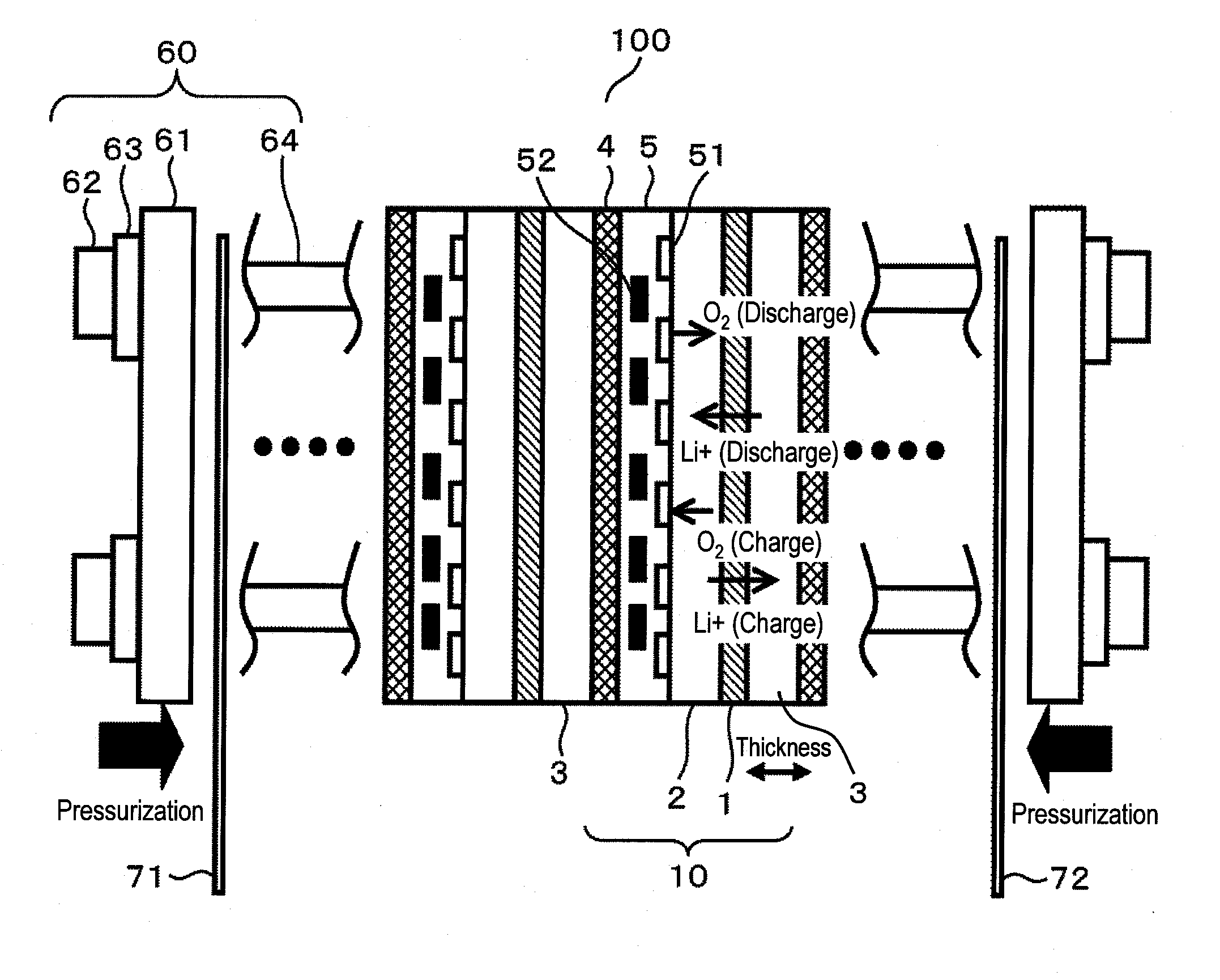
[0052]FIG. 1 illustrates a cross-sectional structure of the rechargeable metal-air battery of the present embodiment.

[0053]As a matter of convenience, the rechargeable metal-air battery of the present embodiment uses lithium as negative-electrode metal to be used for a negative electrode and a nonaqueous solvent as an electrolytic solution.

[0054]Note that zinc, aluminum, magnesium, or the like may be used as the negative-electrode metal, in addition to lithium. In addition, an aqueous solvent may be used as the electrolytic solution.

[0055]Furthermore, although in the present embodiment, metal is used for the negative electrode, the negative electrode may not be made of metal. Any material which undergoes dimensional change upon charging and discharging, as will be described later, results in advantageous effects of the present invention available. Therefore, a carbon material or an oxide material may be used, as long as the material can store and release metal ions. In the case of a...

embodiment 2

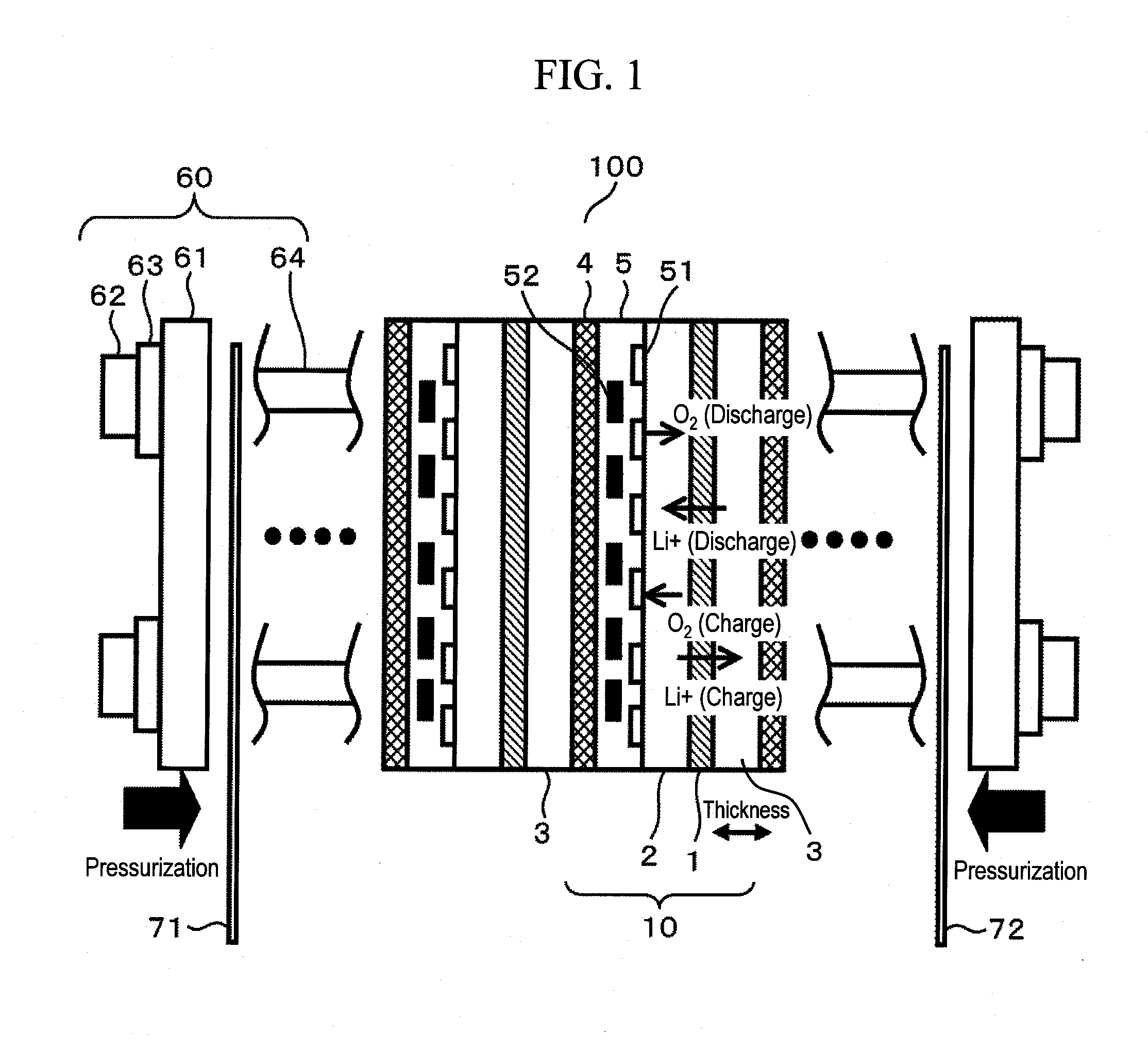
[0098]The dimension-absorbing member 4 and the gas-supplying member 5 may at least be able to functionally satisfy two requirements, i.e., the members can (1) absorb dimensional changes and (2) supply gases, respectively.

[0099]FIG. 2 is a schematic view illustrating an embodiment in which a dimension-absorbing member and a gas-supplying member are integrated with each other.

[0100]As illustrated in FIG. 2, a reaction gas flow path 51 is provided in a porous body 4a having elastic deformation capacity. The advantageous effects of the present embodiment are also attained by performing a sealing treatment with a reaction gas sealer 53, so that a reaction gas flowing through this flow path flows into the positive electrode 2 alone.

[0101]This sealing treatment can be performed in a simplified manner by impregnating the porous body with a sealing agent. Thus, it is possible to reduce the number of components and decrease a height in the stacking direction of the battery.

[0102]This sealing ...

embodiment 3

[0103]The pressure-applying unit 60 is not limited to the one illustrated in FIG. 1. Alternatively, the pressure-applying unit 60 may be configured so that stacked cells are in a state of being pressurized while in use.

[0104]FIG. 3 is a schematic view illustrating an embodiment in which the pressure-applying unit is simplified.

[0105]FIG. 3 illustrates a configuration in which a tightening battery container 65 and an insulating cushion 66 are disposed.

[0106]This is an example in which a pressure is applied by disposing the insulating cushion 66, and then a rechargeable metal-air battery as a whole is fixed in a canned manner with the battery container 65 and a closing cover 67.

[0107]As the insulating cushion 66, rubber, for example, may be used.

[0108]As the battery container 65, metal or a laminate film may be used.

[0109]As a method of assembly, unit cells 10 are stacked in the battery container 65, current terminals 71 and 72 and an insulating cushion 66 are stacked, a pressure is a...


PUM


Abstract

The present invention is intended to suppress the increase of contact resistance due to dimensional changes at the time of charge and discharge in a rechargeable metal-air battery, thereby improving battery performance and service life. The rechargeable metal-air battery of the present invention includes a negative electrode for storing and releasing metal ions; a positive electrode using oxygen as an active material; and an electrolyte membrane placed between the negative electrode and the positive electrode, and is characterized in that a flexible dimension-absorbing member is disposed on the negative electrode side, wherein the dimension-absorbing member is an elastic body formed of a substance which changes reversibly.

Description

BACKGROUND OF THE INVENTION[0001]1. Field of the Invention[0002]The present invention relates to a metal-air battery using oxygen as a cathode active material, and more particularly, to a rechargeable metal-air battery capable of charge and discharge.[0003]2. Background Art[0004]For reasons of increasing awareness of environmental protection and energy saving in recent years, there is fierce competition in the automotive industry to develop a hybrid electric vehicle (HEV) which concomitantly uses motors driven by gasoline and electricity and an electric vehicle (EV) driven by an electric motor alone, as substitute for conventional gasoline-fueled automobiles.[0005]The characteristics of a storage battery serving as a source of electrical energy supply have a great influence on the performance of these electric vehicles. Consequently, battery manufacturers affiliated with respective electric vehicle manufacturers are engaged in fierce competition to develop a rechargeable lithium-ion...

Claims


Application Information

Patent Timeline
IPC IPC(8): H01M12/06H01M10/60H01M10/613H01M10/617H01M10/625H01M10/633H01M10/637H01M10/654H01M10/655H01M10/6556H01M10/6563H01M10/6568H01M12/08
CPCH01M4/382H01M4/405H01M4/64H01M2300/0025H01M12/08H01M2004/027H01M4/74Y02E60/10
Inventor TAKAHASHI, SHINYOSHIDA, KAZUHIROKOHNO, KAZUSHIGE
Owner HITACHI LTD
Why Eureka
Try Eureka