Starter controller

a starter and controller technology, applied in the direction of engine starters, machines/engines, instruments, etc., can solve the problems of affecting the operation of the starter motor, the temperature setting of the air-conditioner is anticipated, and the inability to suppress the current in the starter motor, so as to increase the rotation load

Inactive Publication Date: 2011-08-11
DENSO CORP
View PDF6 Cites 48 Cited by
  • Summary
  • Abstract
  • Description
  • Claims
  • Application Information

AI Technical Summary

Benefits of technology

[0090]The engine is cranked when the on-state fixation abnormality detection processing at restart is performed. The engine is not cranked when the on-state fixation abnormality detection processing at non-start timing is performed. The current flowing through the starter motor in the former case is larger than the current flowing through the starter motor in the latter case by the increase amount of the rotation load of the motor. Therefore, the output voltage of the power supply tends to decrease in the former case

Problems solved by technology

That is, there is a possibility that the inrush current to the starter motor cannot be suppressed in the restart of the engine, so the power supply voltage falls and a certain controller in the vehicle is reset.
For example, if a controller that controls the starter or fuel injection to the engine is reset, a problem that the restart of the engine takes a long time is anticipated.
For example, if a device that controls a

Method used


Image

  • Starter controller
  • Starter controller
  • Starter controller

Examples


first embodiment

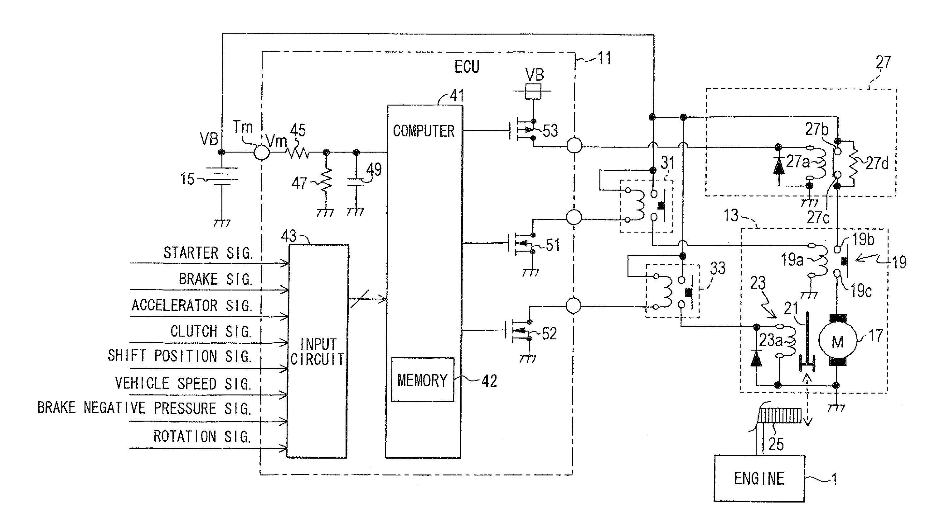
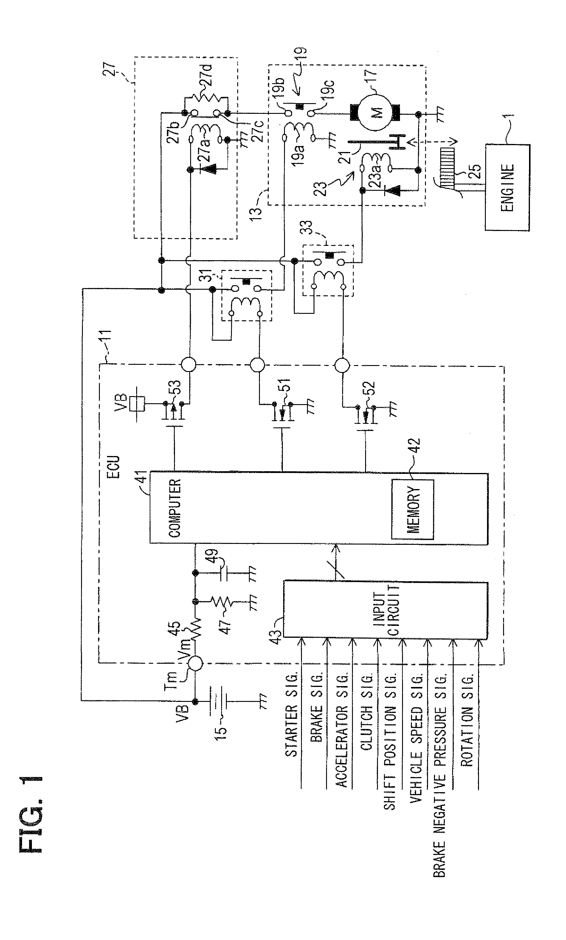
[0129]FIG. 1 is a schematic construction diagram showing an ECU 11 according to a first embodiment of the present invention and peripheral devices of the ECU 11. The ECU 11 performs control of a starter 13 for starting an engine 1 of a vehicle (not shown). The ECU 11 also performs idle reduction control for automatically stopping and automatically starting the engine 1. Following explanation will be given on an assumption that a transmission of the vehicle is a manual transmission.

[0130]The ECU 11 receives inputs of a starter signal, which becomes an active level when a vehicle driver performs a starting operation (e.g., manipulation to twist key put in key cylinder to start position or manipulation to push start button), a brake signal from a sensor for detecting whether a brake pedal is stepped on, an accelerator signal from a sensor for detecting whether an accelerator pedal is stepped on, a clutch signal from a sensor for detecting whether a clutch pedal is stepped on, a shift p...

second embodiment

[0224]Next, a second embodiment of the present invention will be explained. As shown in FIG. 11, in the second embodiment, the ICR relay 27 is not provided outside the ECU 11 unlike the first embodiment. Instead, an inrush current suppression circuit 28 that has the same function as the ICR relay 27 is provided inside the ECU 11.

[0225]The inrush current suppression circuit 28 has a transistor group 28a provided in series between the output terminal of the ECU 11 connected to the contact 19b of the electromagnetic switch 19 and the line of the battery voltage VB inside the ECU 11. The inrush current suppression circuit 28 further has a booster circuit 28b for switching on the transistor group 28a and a resistor 28c provided in parallel to the transistor group 28a between the output terminal of the ECU 11 and the line of the battery voltage VB inside the ECU 11.

[0226]The transistor group 28a consists of multiple transistors parallel to each other. In the present embodiment, each trans...

third embodiment

[0231]Next, a third embodiment of the present invention will be described. As shown in FIG. 12, in the third embodiment, a starter 14 is used in place of the starter 13 of the first embodiment. The starter 14 is constructed such that the action for engaging the pinion gear 21 with the ring gear 25 and the energization to the motor 17 are performed in conjunction with each other. That is, the starter 14 cannot operate the pinion gear 21 and the motor 17 independently from each other. The starter 14 is a reinforced starter that has reinforced parts and that has an increased operable time number as compared to a starter mounted on a vehicle that does not perform the idle reduction.

[0232]More specifically, if the coil 23a of the pinion actuation solenoid 23 of the starter 14 is energized, the pinion gear 21 protrudes and engages with the ring gear 25. In addition, due to an electromagnetic force caused by the energization to the coil 23a, the contacts 19b, 19c of the electromagnetic swi...


PUM


Abstract

An idle reduction vehicle has a relay in a power supply line from a battery to a starter motor. The relay is driven between a contact-side state, in which contacts short-circuit, and a resistor-side state, in which the contacts are opened and a resistor is serially inserted into the power supply line. At an engine restart from idle reduction, an ECU drives the relay to the resistor-side state and starts energization to the motor, thereby suppressing an inrush current. The ECU detects a contact-side state fixation abnormality of the relay based on a battery voltage at the time when the ECU drives the relay to the resistor-side state and energizes the motor. The ECU detects a resistor-side state fixation abnormality of the relay based on the battery voltage at the time when the ECU drives the relay to the contact-side state and energizes the motor.

Description

CROSS REFERENCE TO RELATED APPLICATION[0001]This application is based on and incorporates herein by reference Japanese Patent Applications No. 2010-27708 filed on Feb. 10, 2010 and No. 2010-156754 filed on Jul. 9, 2010.BACKGROUND OF THE INVENTION[0002]1. Field of the Invention[0003]The present invention relates to a controller of a starter that cranks an engine of a vehicle to start the engine.[0004]2. Description of Related Art[0005]In recent years, a vehicle (automobile) having an engine automatic stop-start system is practically used, for example, as described in Patent document 1 (JP-A-H11-30139). Generally, the engine automatic stop-start system is called an idle reduction system or an idling reduction system. The engine automatic stop-start system automatically stops an engine if a predetermined stop condition is satisfied. Thereafter, the engine automatic stop-start system automatically starts the engine if a predetermined start condition is satisfied.[0006]Patent document 2 ...

Claims


Application Information

Patent Timeline
IPC IPC(8): F02N11/08G06F19/00
CPCF02N11/0862F02N11/087F02N2250/02F02N2200/043F02N2200/044F02N11/108
Inventor NAKAMURA, RYOUTA
Owner DENSO CORP
Why Eureka
Try Eureka