Radial flow reactor with movable supports

a technology of radial flow reactor and movable supports, which is applied in the direction of physical/chemical process catalysts, separation processes, manufacturing tools, etc., can solve the problems of increasing the magnitude of thermally induced loads, increasing the cost of fuel, and increasing the size of vessels, so as to reduce thermally induced stresses and loads, and mitigate the adverse effects of thermally induced mechanical stresses

Inactive Publication Date: 2011-08-25
PRAXAIR TECH INC
View PDF14 Cites 21 Cited by
  • Summary
  • Abstract
  • Description
  • Claims
  • Application Information

AI Technical Summary

Benefits of technology

The present invention is a radial flow reactor used in gas separation processes and particularly for purification of air by adsorption and / or a catalytic or non-catalytic reaction. The reactor has two concentric porous internal baskets which confine the active material, typically a free-flowing particulate solid, within the baskets and within the cylindrical shell. The baskets are rigidly supported at both the top and bottom ends of the vessel and have walls that are axially flexible and radially rigid to minimize thermally induced stresses and loads. The reactor vessel has support columns that are affixed to a bottom plate which is affixed to the bottom of the baskets and are movable. Preferable, the support columns are a split support column assembly that provides means to simply and effectively pre-stress the internal baskets, defined as the act of placing the baskets in tension at ambient temperature, thereby mitigating the adverse effects of thermally induced mechanical stresses.

Problems solved by technology

Such demands are partially driven by the ever-increasing cost of fuel and the need for various chemical feed stocks.
This presents a challenge to reactor designers when trying to control the size of the reactor since higher throughput of feed air demands a proportional increase in the frontal flow area provided by the vessels resulting in larger, more costly vessels.
Such thermally induced loads create significant mechanical stresses on all elements of the internal basket assemblies, the magnitude of such induced loads increases with increasing temperature difference.
Axial and radial displacement of the basket walls may also result in compression of the bed of active material and the material particles may migrate or be damaged as a result of the basket wall movement.
In the worst case, these effects can cause physical breakdown of the active material and / or mechanical failure of the basket assemblies.
Conversely, the internal components of the reactor experience these temperature variations directly, resulting in thermal expansions and contractions and the associated induced loads and stresses.
Further, the thermally induced mechanical stresses limit the temperature range over which conventional radial flow reactors may operate and these limitations are amplified as the size of the reactor increases thereby limiting the size and application of the reactors.
The teachings in the art are varied and inconsistent with respect to the design of radial flow reactors; particularly for vessels undergoing thermal cycling.
All of these designs have various deficiencies, most notably a continuing problem with thermally induced stress, shearing, and possible damage to the equipment and active material.
Notwithstanding these teachings, there is no clear direction for the design of a radial flow reactor to mitigate or eliminate these problems.
Moreover, there are no teachings on methods for pre-stressing the internal baskets or on reactors designed for this purpose.

Method used


Image

  • Radial flow reactor with movable supports
  • Radial flow reactor with movable supports
  • Radial flow reactor with movable supports

Examples


Embodiment Construction

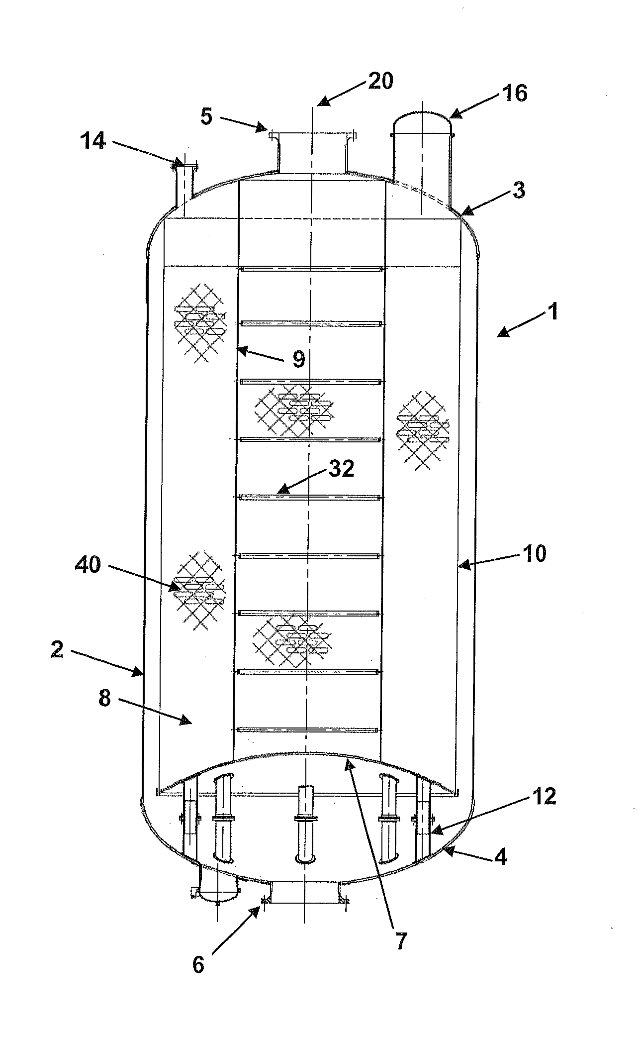
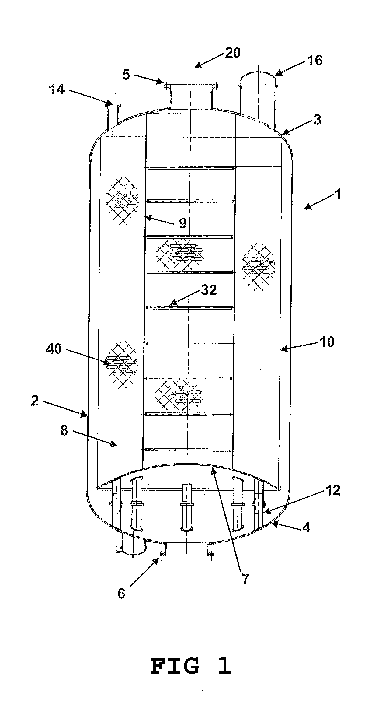
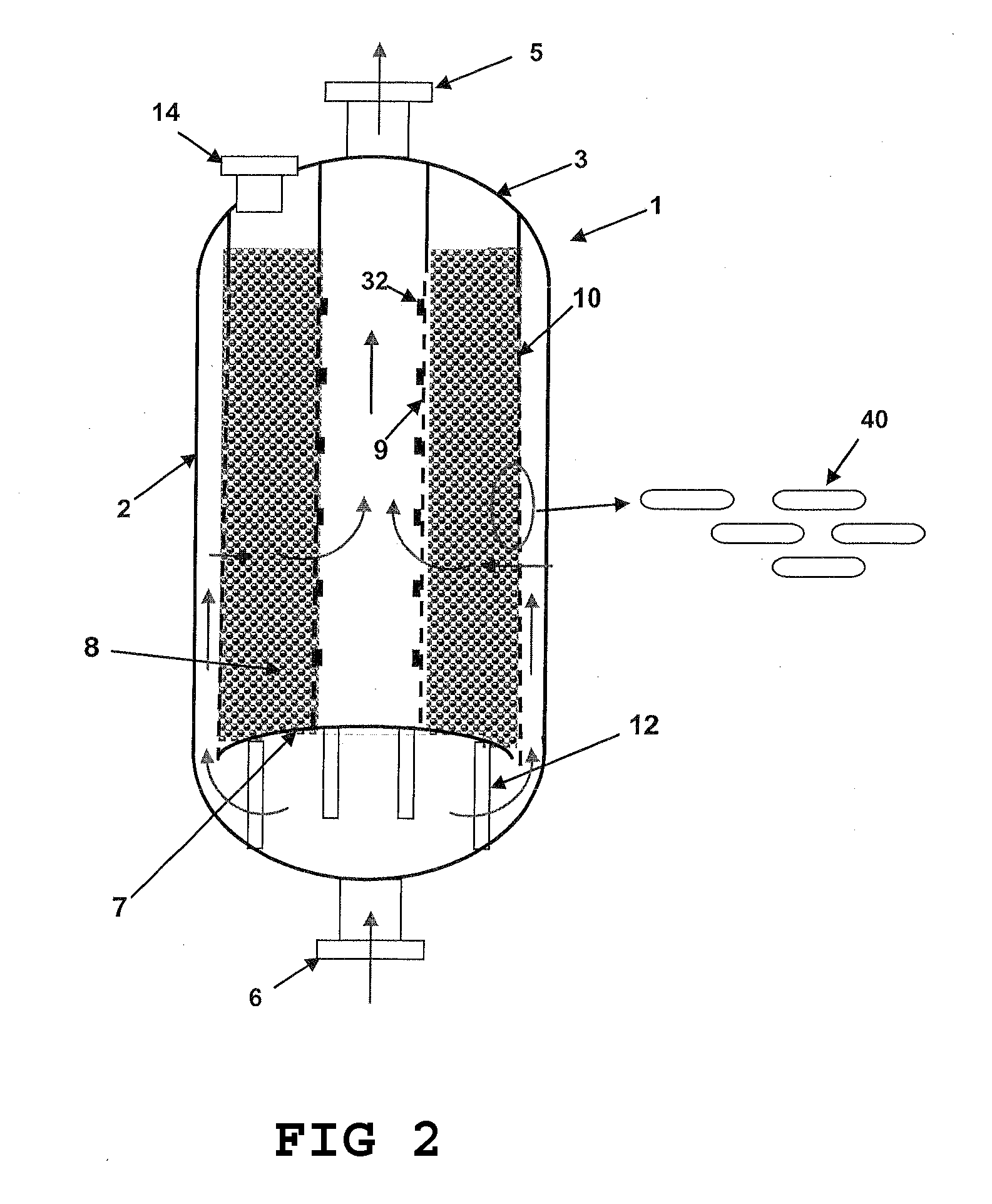
FIGS. 1-7 illustrate the basic structure of one embodiment of the radial flow pressure vessel of this invention and certain of its components. The cross-sectional view of FIG. 1 illustrates the essential features of this embodiment and of the invention, but does not show all fastener means, conduits and apparatus details or other aspects of the invention which are understood and readily apparent to one skilled in the art. FIG. 2 is a schematic of the vessel showing essentially the same features as in FIG. 1 and additionally the gas flow path through the vessel. The Figures do not represent actual dimensions.

Referring to FIG. 1, a substantially cylindrical radial flow reactor vessel (1) on a vertical longitudinal axis (20). The vessel has an outer shell (2) with upper (3) and lower (4) hemispherical caps as generally known in the industry. Lower cap (4) has inlet (6) for receiving a feed gas and upper cap (3) has outlet (5) for the exit of the product gas in normal operation. In prep...


PUM

PropertyMeasurementUnit
thicknessaaaaaaaaaa
thicknessaaaaaaaaaa
tensionaaaaaaaaaa

Abstract

A radial flow reactor vessel is disclosed for use in gas purification, separation or reaction processes and most suitably used in prepurification processes. The reactor has internal baskets for confining a bed of active material. The baskets are rigidly supported at both the top and bottom ends of the reactor and have walls that are axially flexible and radially rigid. The vessel has multiple movable support columns designed to facilitate pre-stressing of the baskets to offset axial compressive loads induced from thermal cycling.

Description

FIELD OF THE INVENTIONThe present invention relates generally to the field of radial flow reactor vessels used in gas purification, separation, and reaction processes. More specifically, this invention relates to radial flow vessels having internal basket assemblies to retain active material used to remove and / or convert one or more components in a feed stream through adsorption and / or catalytic or non-catalytic reactions and having movable support columns.BACKGROUND OF THE INVENTIONThe demand for higher reactor throughput continues to increase for a variety of industrial processes linked to oil and gas recovery, alternative fuel production, sustainability of the environment and process emissions. Such demands are partially driven by the ever-increasing cost of fuel and the need for various chemical feed stocks. One example is the demand for larger cryogenic air separation units (ASUs) to meet the growing needs for large quantities of oxygen and nitrogen used in various industrial p...

Claims


Application Information

Patent Timeline
Patent Type & Authority Applications(United States)
IPC IPC(8): B01D53/88B01J8/02B01D53/047B01D53/86
CPCB01D53/0431Y10T29/49863B01D53/047B01D53/0476B01D2253/104B01D2253/108B01D2257/504B01D2257/7022B01D2257/80B01D2258/06B01D2259/40086B01D2259/4146B01J8/008B01J8/0214B01J2208/00884B01J2219/185B01J2219/1943Y02C10/08B01D53/0462Y02C20/40
Inventor ACKLEY, MARK WILLIAMCELIK, CEM E.NOWOBILSKI, JEFFERT JOHNSCHNEIDER, JAMES STANLEY
Owner PRAXAIR TECH INC
Why Eureka
Try Eureka