MRI apparatus and method with moving field component

a field component and imaging system technology, applied in the direction of nmr measurement, instruments, nuclear magnetic resonance analysis, etc., can solve the problems of conductive transducers and instrumentation systems within the field gradient, the inability to use surface coils as transmit coils, and the range of system limitations and deleterious effects

Active Publication Date: 2011-09-01
THE UNIV OF QUEENSLAND
View PDF12 Cites 37 Cited by
  • Summary
  • Abstract
  • Description
  • Claims
  • Application Information

AI Technical Summary

Problems solved by technology

Unfortunately surface coils are not feasible as transmit coils, since they can not excite a large proportion of anatomy with a uniform spatial distribution of the RF field B1.
During imaging, pulsing of gradient coils brings about a range of system limitations and deleterious effects.
Conductive transducers and instrumentation systems within the field gradients will also be vulnerable to induced voltages due to possible conductive paths.
The interaction of gradient-pulsed fields with conducting MRI system components stimulates spatially and temporally complex eddy currents that can significantly affect the intended space-time qualities of the field gradients along with torques / forces that often introduce significant levels of acoustic noise and vibration in the system.
Although a significant research contribution was made in the last two-three decades on these well-known issues, there is yet no full solution that completely eradicates the aforementioned issues and side-effects caused by switching of MR gradient coils.
However, increasing the number of receiver coils, increases the number of lumped components and hence the difficulties to properly decouple the coils.
Additionally, increasing the number of required hardware channels increases the system cost.
However, at high field strength, field / tissue interactions become pronounced causing dielectric resonance effects, which precipitate the RF inhomogeneity.
Unfortunately, the RF transmission time can be quite long as the applied gradient fields are limited by the slew rates of the gradient coils.
Akin to receive SENSE, transmit SENSE suffers from significant mutual coupling associated with large coil arrays.
Therefore the trend for a larger scan time reduction necessitates an even larger number of transceive coils and channels, which ultimately augments the physical complexity and the cost of the apparatus.

Method used


Image

  • MRI apparatus and method with moving field component
  • MRI apparatus and method with moving field component
  • MRI apparatus and method with moving field component

Examples


experiment 1

ty and In-Vivo MRI with Rotating Transceive

[0266]In this experiment, a Fast Low Angle SHot (FLASH) imaging sequence was selected to obtain an axial image with a slice thickness of 5 mm. The field of view (FOV) for image acquisition was set to 25 cm×25 cm and the matrix size was 256×256. A 3 ms duration Gauss pulse was used to nutate the spins by 45°, while the time of repetition (TR) was 70 ms.

[0267]The transceive coil 13 is used to both transmit the RF energy and receive the FIDs (i.e. no pin-diodes are used for switching). The reception of FIDs during RF coil 13 rotation is viable, because the frequency of Larmor precession (f0=85.45 MHz) is much higher than the frequency of rotation (i.e. 18.4 Hz), and so in the reference frame of spins, the coil 13 may be regarded to be almost stationary.

[0268]FIG. 6 is an axial sensitivity profile and illustrating the profile of the RF field B1 obtained with the described FLASH imaging sequence when the coil is fixed at 0° angular position. The...

experiment 2

mity with Rotating Transmit and Stationary Receive MR

[0274]In this example, instead of receiving the FID or echo signals with the same coil 13, a separate 2-element receive-only phased array coil 12 was constructed, as shown in FIG. 5G above. The receive coils 12 are situated on the outer surface of the fixed cylinder 11. The RF coil 13 on rotating cylinder 14 is rotated and used as transmit-only coil. Fast pin-diode switching systems are included in both coils 13, 12, which effectively open-circuits one coil from another whenever the other coil 13, 12 is in operation.

[0275]FIG. 10 illustrates the image of the homogenous cylindrical phantom 5 acquired with this setup. In this image, a top part of the cylindrical phantom image appears dark due to the presence of an air bubble. The dark artefacts on the periphery of the cylindrical phantom image are due to plastic holders which were used initially to support the cylindrical phantom inside the sample tube 11. These supports were remove...

experiment 3

ional RF Pulses with Rotating Transceive MR

[0276]For spatially selective magnetization excitation of four Gauss shapes, the multi-dimensional RF pulses and gradient field waveforms were computed assuming a uniform profile for the RF field B1, as shown in FIG. 11.

[0277]A Multi-Spin Multi-Echo (MSME) imaging pulse sequence was selected, with the RF pulse train being transmitted during a time period of 40 ms while applying transverse gradients as shown in FIG. 11. While this excites a volume of spins, the slice position was selected during the application of the 180° refocusing RF pulse, thereafter, frequency and phase encoding was performed. The thickness of the selected slice was chosen to be 5 mm, while the FOV was set to 22 cm×22 cm with a matrix size of 256×256.

[0278]The RF coil 13 operating in transceive mode and rotating at ˜1000 rpm was engaged in this experiment. Note that the receive-only phased array coil 12 is removed. The TR and TE were set to 80.2 ms and 38.5 ms, respecti...


PUM


Abstract

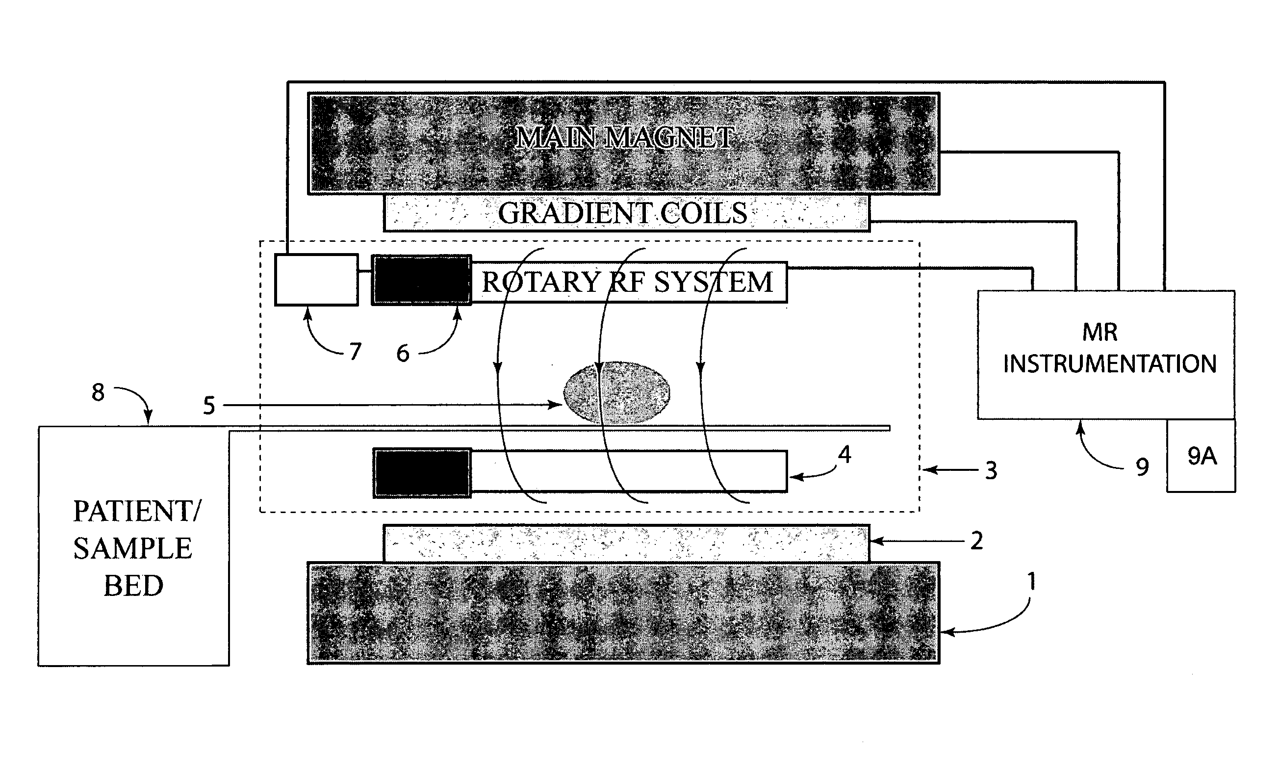
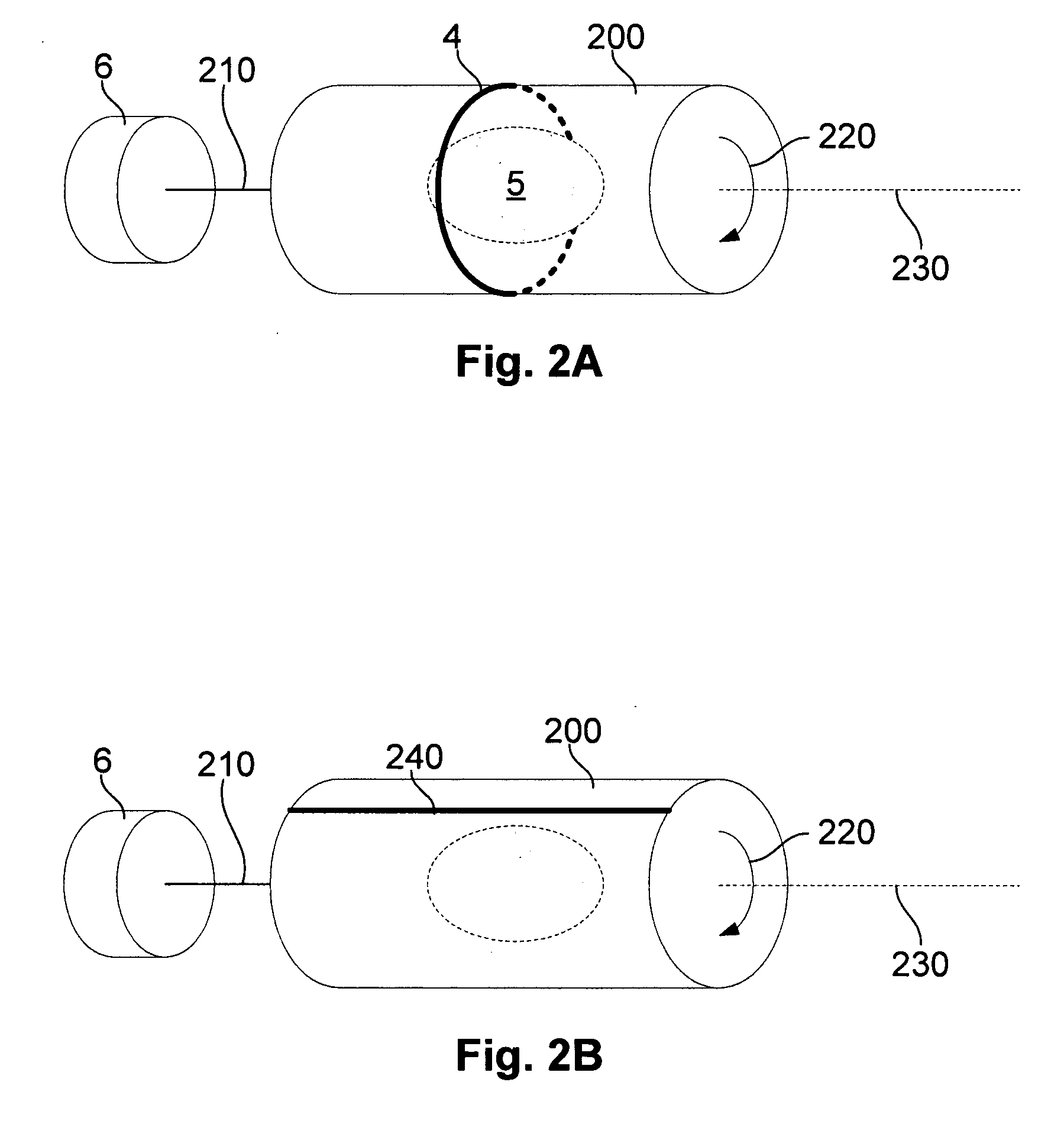
Apparatus for use in a magnetic resonance imaging system, the imaging system generating a magnetic imaging field in an imaging region (5), the apparatus including at least one coil for at least one of transmitting, receiving or transceiving an electromagnetic field, a field component (4) (such as a coil or a shield) and a drive (6) coupled to the field component for moving the field component (4) relative to the imaging region (5) to thereby modify the electromagnetic field during imaging process. The same concept can also be applied to nuclear imaging or nuclear spectroscopy apparatus.

Description

BACKGROUND OF THE INVENTION[0001]The present invention relates to apparatus and a method for moving a field component in an imaging system, and in particular, to apparatus and a method for moving a shield or coil in an imaging system, such as a magnetic resonance imaging (MRI) system.DESCRIPTION OF THE PRIOR ART[0002]The reference in this specification to any prior publication (or information derived from it), or to any matter which is known, is not, and should not be taken as an acknowledgment or admission or any form of suggestion that the prior publication (or information derived from it) or known matter forms part of the common general knowledge in the field of endeavour to which this specification relates.[0003]In MRI, when a substance such as the human tissue is exposed to a strong and uniform polarizing static magnetic field B0, the spins of abundant water hydrogen protons in the tissue align their individual magnetic moments along the magnetic field B0, in a parallel or anti...

Claims


Application Information

Patent Timeline
Patent Type & Authority Applications(United States)
IPC IPC(8): G01R33/48
CPCG01N24/08G01R33/34007G01R33/34046G01R33/34076G01R33/46G01R33/5659G01R33/5612G01R33/563G01R33/56341G01R33/5635G01R33/56366G01R33/5611G01R33/3635G01R33/422G01R33/446
Inventor TRAKIC, ADNANWEBER, EWALDLI, BING KEONGWILSON, STEPHEN JAMESHUA, WANGLIU, FENGCROZIER, STUART
Owner THE UNIV OF QUEENSLAND
Why Eureka
Try Eureka