Liquid ejection head, liquid ejection device

Inactive Publication Date: 2011-09-08
SEIKO EPSON CORP
View PDF20 Cites 7 Cited by
  • Summary
  • Abstract
  • Description
  • Claims
  • Application Information

AI Technical Summary

Benefits of technology

[0012]The piezoelectric layer is preferably a spontaneously oriented film. Such a configuration makes it possible to provide a liquid ejection head having a piezoelectric layer obtained without having to orient the material under an applied magnetic field, provide the substrate of the piezoelectric film with a layer for controlling orientation, or perform another similar operation.
[0013]The piezoelectric layer preferably further includes SiO2. Such a configuration makes it possible to provide a liquid ejection head having piezoelectric elements with excellent insulating properties.
[0014]The piezoelectric layer preferably contains SiO2 in an amount of 0.5 mol % or more and 5 mol % or less with respect to the perovskite compound. Such a configuration makes it possible to provide a liquid ejection head having a piezoelectric layer with dependably low lead content, high relative dielectric constant, and excellent insulating properties.
[0015]A liquid ejection device according to another aspect of the present invention includes the liquid ejection head of the preceding aspect. According to this aspect, the liquid ejection device is provided with a liquid ejection head having a piezoelectric layer with low lead content and a high relative dielectric constant, thereby affording a device with excellent ejection characteristics and negligible environmental impact.

Problems solved by technology

A problem with such BiFeO3 based piezoelectric materials which contain Bi and Fe is that piezoelectric characteristics (strain rate) tend to be low owing to the relatively low relative dielectric constant.
This problem is not limited to liquid ejection heads typified by inkjet heads, and similar problems are encountered with piezoelectric elements of actuator devices installed in other types of devices as well.

Method used


Image

  • Liquid ejection head, liquid ejection device
  • Liquid ejection head, liquid ejection device
  • Liquid ejection head, liquid ejection device

Examples


first embodiment

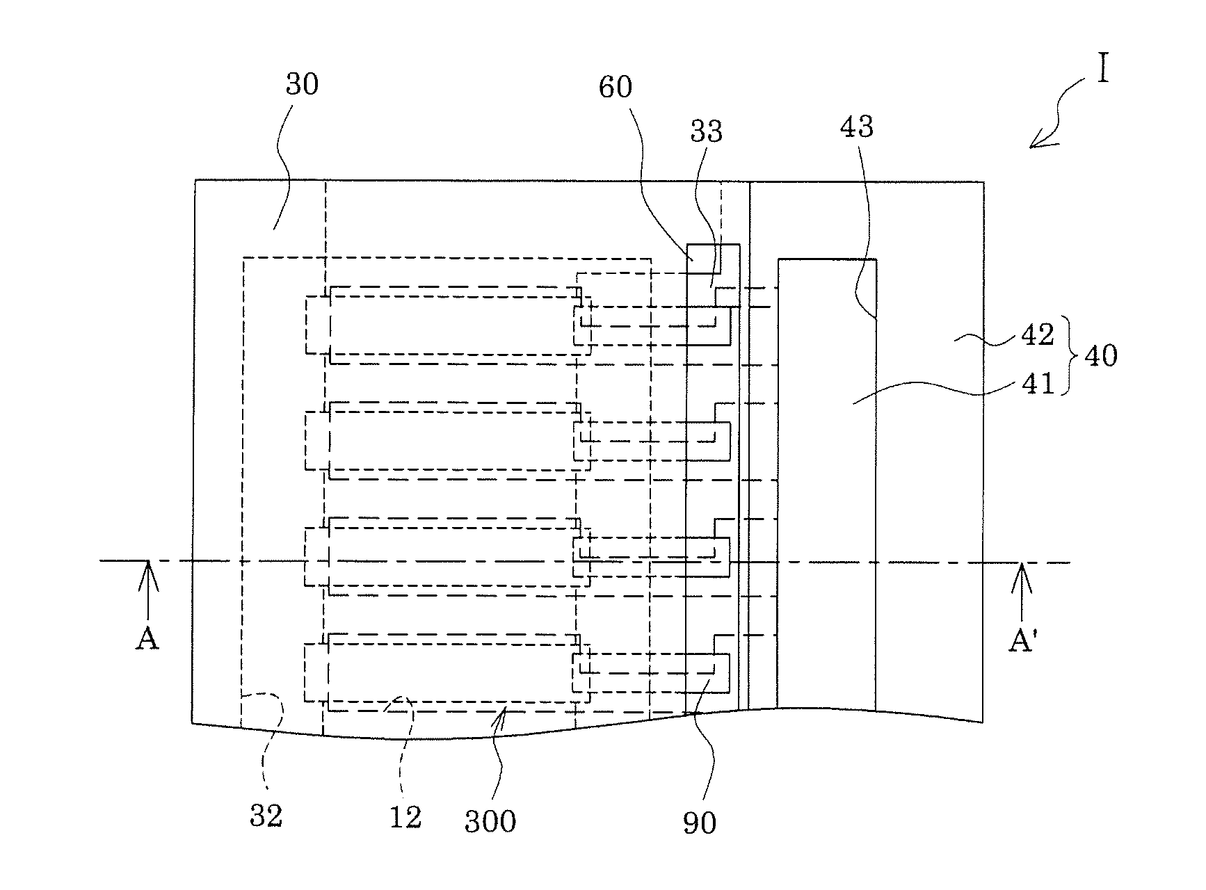
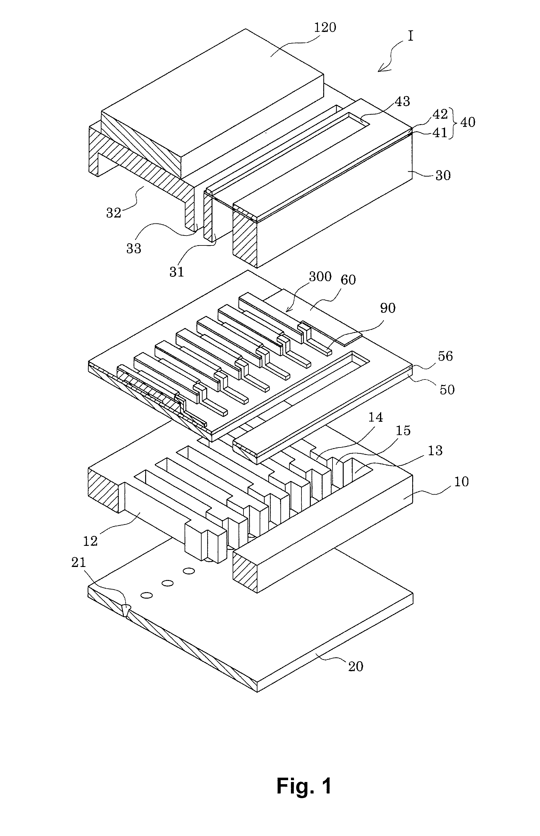
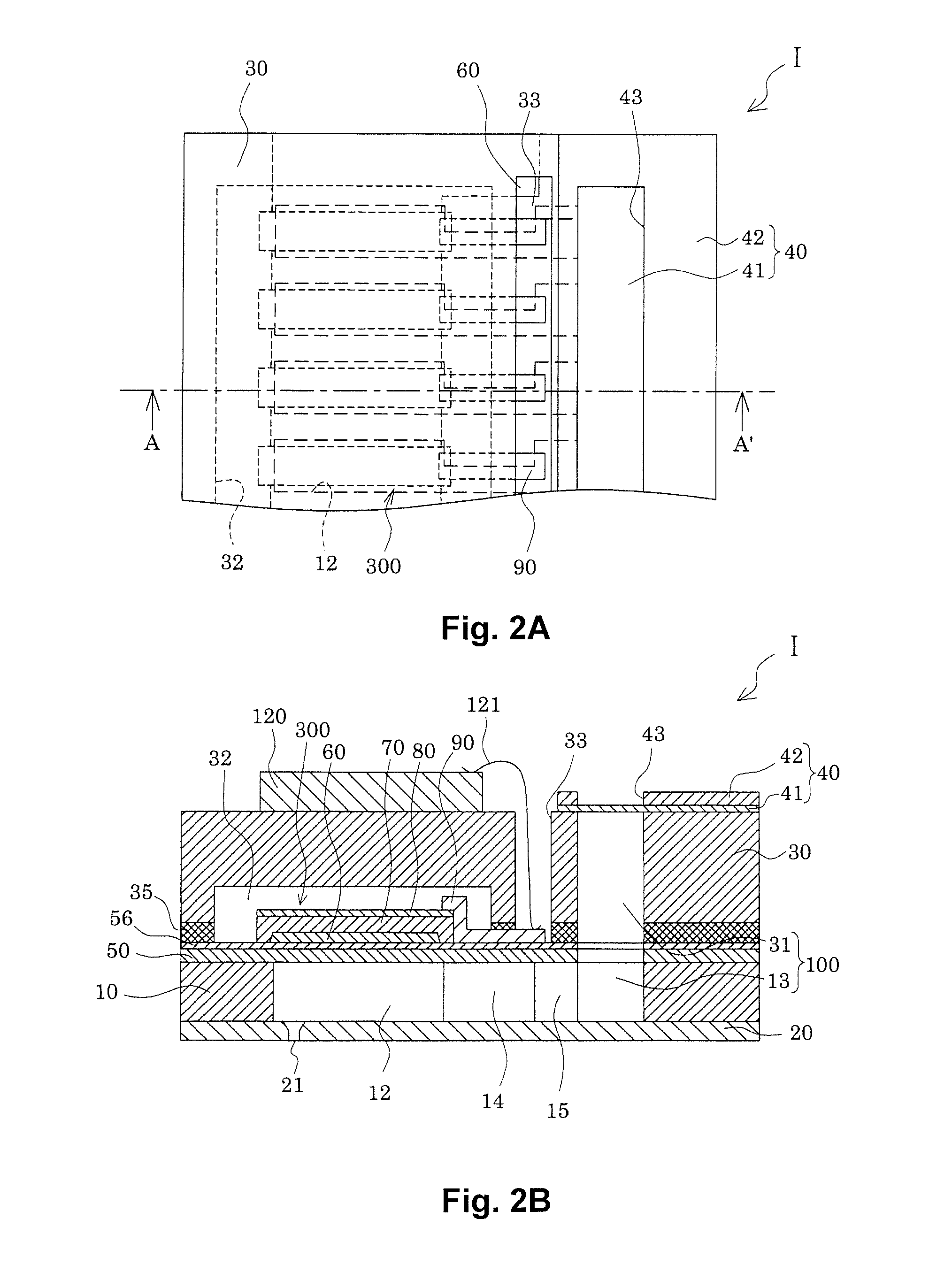
[0035]FIG. 1 is an exploded perspective view showing a simplified configuration of an inkjet recording head as an example of a liquid ejection head according to a first embodiment of the invention; and FIG. 2A is a plan view and FIG. 2B is a cross sectional view thereof across A-A′.

[0036]As shown in FIGS. 1 and 2, in the present embodiment there is provided a flow-defining substrate 10 made of a single-crystal silicon substrate with a resilient film 50 of silicon dioxide formed on one face.

[0037]A plurality of pressure generation chambers 12 are arrayed along the width direction of the flow-defining substrate 10. A communicating portion 13 is formed in a zone situated at the lengthwise outer ends of the pressure generation chambers 12 of the flow-defining substrate 10, and the communicating portion 13 communicates with the pressure generation chambers 12 via ink supply channels 14 and communicating channels 15 which are individually provided to the pressure generation chambers 12. T...

first working example

[0061]First, an SiO2 film having film thickness of 400 nm was formed by thermal oxidation of the surface of a silicon substrate. Next, using an RF sputtering method, a TiAlN film having film thickness of 100 nm was formed over the SiO2 film. Next, using a DC sputtering method, an Ir film having film thickness of 100 nm and an IrO2 film having film thickness of 30 nm were formed successively over the TiAlN film, and a Pt film oriented in the (111) plane was formed thereon by a vapor deposition method, to form the first electrode 60.

[0062]Next, a piezoelectric layer was formed on the first electrode by a spin coating method. The method is as follows. First, metal compounds of Bi, Fe, Mn, Ba, Ti, and Si, more specifically bismuth octylate, iron octylate, manganese octylate, barium octylate, titanium octylate, and SiO2, together with an octane solvent, are mixed in prescribed proportions to prepare a precursor solution. In the resultant solution the total number of moles of Bi, Fe, Mn, ...

second working example

[0064]A piezoelectric element 300 was formed analogously to the first working example, except that the Si compound was not added to the precursor solution, and the piezoelectric material of the piezoelectric layer 70 was composed of the perovskite compound 0.75 Bi(Fe0.95Mn0.05) O3-0.25 BaTiO3.


PUM

PropertyMeasurementUnit
Thicknessaaaaaaaaaa
Piezoelectricityaaaaaaaaaa

Abstract

A liquid ejection head including a piezoelectric element having a piezoelectric layer and electrodes The piezoelectric layer is 3 μm or less in thickness. The piezoelectric layer is made of a piezoelectric material including bismuth manganate ferrate and barium titanate. The piezoelectric layer is preferentially oriented with the (110) plane.

Description

CROSS-REFERENCE TO RELATED APPLICATIONS[0001]This application claims priority to Japanese Patent Application No. 2010-045973 filed on Mar. 2, 2010 and Japanese Patent Application No. 2011-014619 filed on Jan. 26, 2011. The entire disclosures of Japanese Patent Application Nos. 2010-045973 and 2011-014619 are hereby incorporated herein by reference.BACKGROUND[0002]1. Technical Field[0003]The present invention relates to a liquid ejection head and a liquid ejection device provided with piezoelectric elements having electrodes and a piezoelectric layer of a piezoelectric material, and adapted to expel droplets of liquid from nozzle openings.[0004]2. Related Art[0005]One known structure for a piezoelectric element has a piezoelectric layer of a piezoelectric material that exhibits an electrical-mechanical conversion function, for example, a crystallized dielectric material, sandwiched by two electrodes. Piezoelectric elements of this kind may be installed in a liquid ejection head to se...

Claims


Application Information

Patent Timeline
IPC IPC(8): B41J2/045B41J2/055B41J2/135B41J2/14B41J2/145C04B35/00C04B35/462H01L41/09H01L41/18H01L41/187H01L41/318H01L41/39
CPCB41J2/14233B41J2002/14241B41J2002/14419C04B35/2633C04B2235/3215C04B2235/3236B41J2/14201C04B2235/3418C04B2235/441C04B2235/768C04B2235/787H01L41/1878H01L41/318C04B2235/3298H10N30/8561H10N30/078
Inventor HAMADA, YASUAKI
Owner SEIKO EPSON CORP
Why Eureka
Try Eureka