Cable having insulation with micro oxide particles

a micro oxide particle and cable technology, applied in the field of cables, can solve the problems of affecting the safety of use of cables, so as to achieve the effect of increasing flame retardancy

Inactive Publication Date: 2011-09-15
GENERAL CABLE TECH CORP
View PDF41 Cites 26 Cited by
  • Summary
  • Abstract
  • Description
  • Claims
  • Application Information

AI Technical Summary

Benefits of technology

[0008]According to an exemplary embodiment, the present invention provides a cable comprising a plurality of conductors where each conductor is surrounded by a layer of insulating material. A jacket encloses the plurality of conductors and the jacket is formed of an insulating material. A separator separates the plurality of conductors and the separator is formed of an insulating material. The insulation material of at least one of the plurality of conductors, the jacket, and the separator includes micro oxide particles to form a composite insulation which has an increased flame retardancy over the insulation material without the micro oxide particles.
[0009]According to another embodiment, the present invention also provides a data cable that comprises a plurality of conductors and each conductor is surrounded by a layer of insulating material. The plurality of conductors are twisted into at least one pair. A jacket encloses the plurality of conductors and is formed of an insulating material. A separator separates the plurality of conductors. The separator is formed of an insulating material. The insulation material of at least one of the plurality of conductors, the jacket, and the separator including micro oxide particles to form a composite insulation which has at least one of an increased flame retardancy and improved electrical properties over the insulating material without the micro oxide particles, such that the cable has an improved electrical performance.

Problems solved by technology

Wire and cable insulation or coating or component compositions are normally quite flammable.
As a result, they can pose a fire hazard in power plants, distribution areas, manholes, and buildings.
Accordingly, various fire codes prohibit the use of cables, particularly in plenum applications, unless they pass certain smoke and flame retardancy tests.
Halogens, however, have a drawback in that the gases evolved (i.e. hydrogen chloride, hydrogen fluoride and hydrogen bromide) during burning, or even merely overheating, are corrosive as well as being toxic which is often limited by building codes or undesirable in some building overheating locations.
A drawback of this system is that the metal hydroxide is polar, which absorbs moisture when the cable is exposed to a wet environment, resulting in a reduction in the electrical insulation properties of the coating composition.
Use of metal hydroxides also limits processing temperature of the insulation.
However, such fluoropolymer materials are expensive and significantly increase manufacturing costs.
Also, FEP has been found to produce smoke under high or intense heat conditions which is often undesirable in building overheating locations.
Some fillers, such as calcium carbonates and kaolins, have been added to insulation; however such fillers are hydrophilic, increase the dissipation factor of the insulation, lower the dielectric constant of the insulation, thereby causing greater attenuation and delay skew.
When the dissipation factor of the insulation is increased, the dielectric constant of the insulation is lower, thereby causing greater attenuation and delay skew.
This increase in dissipation factor of the insulation cause greater attenuation of the signal along the length of the transmission line.
Multiplatlet clays that are treated with ionic or cationic exfoliating agents have also been added to insulation, however such additives cause undesirable dielectric properties, they impart stiffness when cables are usually desired to be flexible, and their high surface areas cause undesirable rheological properties, such as increased viscosity, thereby limiting the amounts that can be added to the insulation.

Method used


Image

  • Cable having insulation with micro oxide particles
  • Cable having insulation with micro oxide particles
  • Cable having insulation with micro oxide particles

Examples


Embodiment Construction

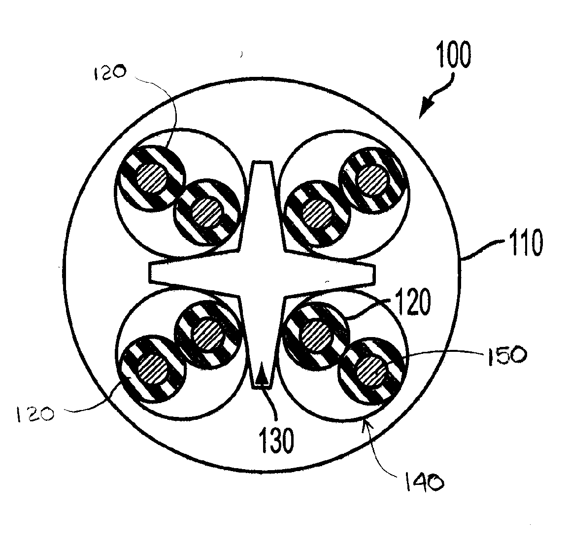
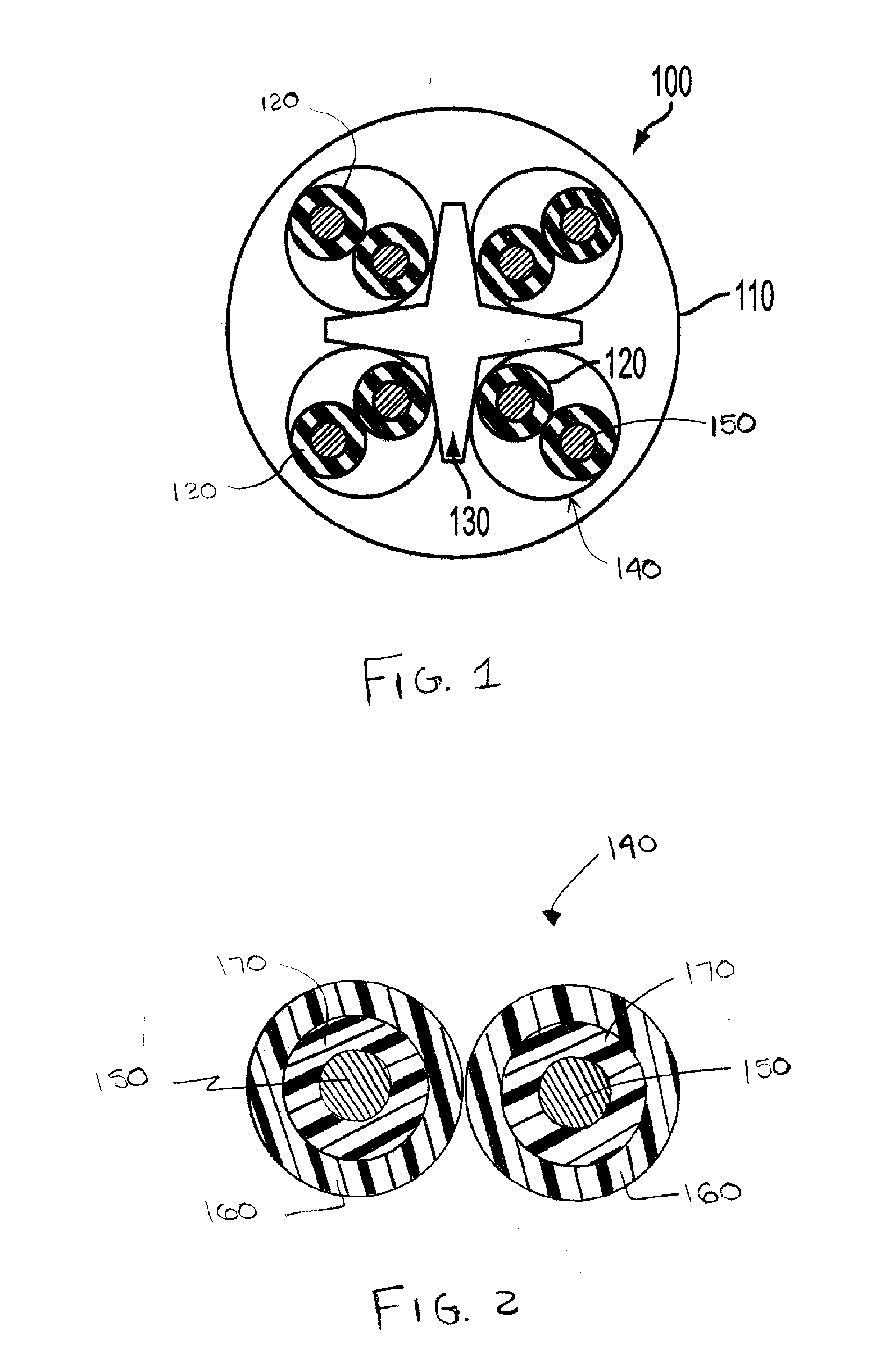
[0017]Referring to FIGS. 1 and 2, the present invention generally relates to a composite insulation for cable and its components that includes added non-porous micro oxide particles to improve the flame retardancy and electrical performance characteristics of the cable while also reducing costs. For example, with the addition of the non-porous micro oxide particles to the insulation, the insulation has (a) a decreased melt flow rate that contributes to a reduction in dripping, i.e. the melt flow index is decreased by up to about 100%, preferably about 3-50%, thereby decreasing the risk of flame spread and exhibiting less smoke when exposed to flame; (b) an increased dielectric constant by about 2-50%, and preferably 3-30%, thereby refining electrical performance; (c) an increased viscosity by 3-100%, preferably by about 3-30%, which improves and simplifies extruding; (d) preferably about 30-100% less transparency so that less, if any, coloring agent is required, to make the insulati...


PUM

PropertyMeasurementUnit
mean particle sizeaaaaaaaaaa
transparencyaaaaaaaaaa
dissipation factoraaaaaaaaaa

Abstract

A cable that comprises a plurality of conductors. Each conductor is surrounded by a layer of insulating material. A jacket encloses the plurality of conductors. The jacket is formed of an insulating material. A separator separates the plurality of conductors. The separator is formed of an insulating material. The insulation material of at least one of the plurality of conductors, the jacket, and the separator includes micro oxide particles to form a composite insulation which has at least one of an increased flame retardancy and improved electrical properties over the insulating material without the micro oxide particles, such that the cable has an improved electrical performance.

Description

RELATED APPLICATION[0001]This application claims priority to U.S. Provisional Application Ser. No. 61 / 313,513, filed on Mar. 12, 2010, and U.S. Provisional Application Ser. No. 61 / 321,360, filed on Apr. 6, 2010, both entitled Insulation With Micro Oxide Particles and Cable Using The Same.FIELD OF THE INVENTION[0002]The present invention relates to a cable that uses insulation with micro oxide particles. More specifically, the present invention relates to insulation with micro oxide particles used with cable and cable components for increasing the flame retardancy and the electrical performance of the cable.BACKGROUND OF THE INVENTION[0003]Wire and cable insulation or coating or component compositions are normally quite flammable. As a result, they can pose a fire hazard in power plants, distribution areas, manholes, and buildings. Ignition can easily occur from overheating or arcing. Accordingly, various fire codes prohibit the use of cables, particularly in plenum applications, unl...

Claims


Application Information

Patent Timeline
Patent Type & Authority Applications(United States)
IPC IPC(8): H01B7/295
CPCH01B7/0216H01B7/295
Inventor SZYLAKOWSKI, GREGG R.ALBRINCK, ALICE C.MCLINN, MATTHEW S.
Owner GENERAL CABLE TECH CORP
Why Eureka
Try Eureka