Methods and apparatus for ultra-sensitive temperature detection using resonant devices

Active Publication Date: 2011-09-22
PENN STATE RES FOUND
View PDF41 Cites 34 Cited by
  • Summary
  • Abstract
  • Description
  • Claims
  • Application Information

AI Technical Summary

Benefits of technology

[0017]Another object, feature, aspect, or advantage of the present invention is an improved sensitivity quartz resonator temperature sensor and method.
[0018]Another object, feature, aspect or advantage of the present invention is a quartz resonator temperature sensor and method which deters mass loading effect.
[0019]Other objects, features, aspects, and advantages of the present invention will become apparent with reference to the accompanying specification.
[0021]In one aspect of the invention, ultra-sensitive temperature measurement is accomplished by placing a quartz resonator-based calorimetric sensor at or near a measurement location, such as might be defined by a reactor chamber or other vessel or location at which temperature is to be monitored during some event or time period. O

Problems solved by technology

However, it has been discovered that conventional uses and modes of operation of such sensors present certain limitations in, inter alia, their use, accuracy, and applications.
For example, current conventional configurations of such sensors raise the following issues:a. Response times. Limita

Method used


Image

  • Methods and apparatus for ultra-sensitive temperature detection using resonant devices
  • Methods and apparatus for ultra-sensitive temperature detection using resonant devices
  • Methods and apparatus for ultra-sensitive temperature detection using resonant devices

Examples


exemplary embodiment 1

A. Exemplary Embodiment 1

General Method, Apparatus and System

[0097]Two prominent aspects are as follows.

[0098]1. Fabrication Method

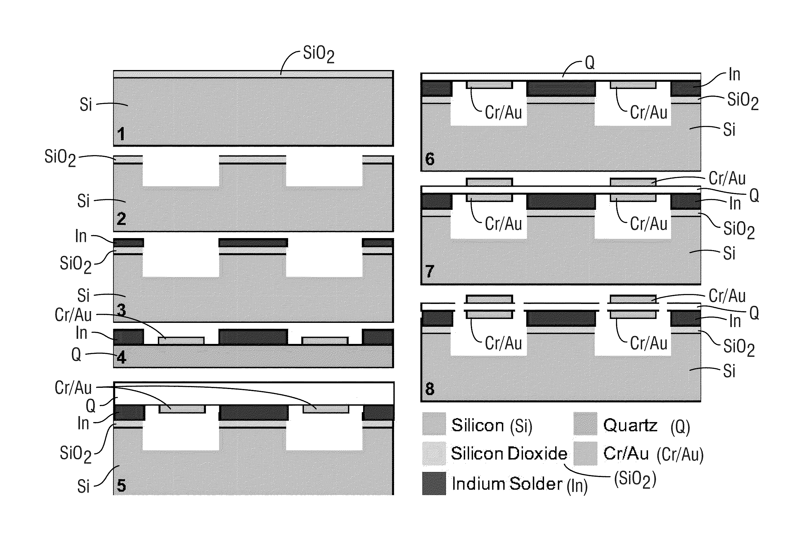
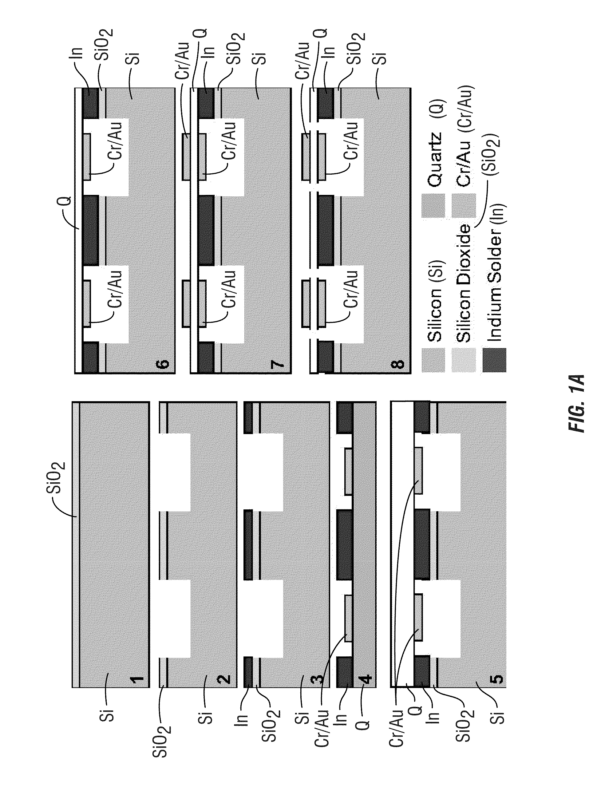
[0099]Fabrication of extremely small thermal mass quartz resonance-based calorimetric sensors allows the sensors to be placed in close proximity to the event to be measured. Similarly, fabrication of extremely small vessels or reaction chambers, and the ability to position the sensors near the event but neither touching the reaction chamber nor requiring placement of the analyte on the sensor, improve sensitivity of the measurements.

[0100]In the examples of Exemplary Embodiments 1-3, Y-cut quartz monolithic crystals are utilized. Micromachining techniques are well-known in the art (see, e.g., Marc J. Madou, “Fundamentals of MicroFabrication, CRC Press, Boca Raton, Fla., USA, 2002, (2nd Edition)).

[0101]Typical conventional quartz elements used in resonant sensors are on the order of 80 to 600 μm thick with resonant frequencies in the range of 3 to 20 MHz ...

exemplary embodiment 2

References for Exemplary Embodiment 2

[0203]1. Karube, K. Sode, and E. Tamiya, Journal of Biotechnology 15, 267-281 (1990).[0204]2. H. C. Cantor, V. Padmanabhan, P. Favreau, and A. Midgley Jr, Endocrinology 137, 2782-2790 (1996).[0205]3. M. Shichiri, M. Sakakida, K. Nishida, and S. Shimoda, Artificial Organs 22, 32-42 (1998).[0206]4. K. Ramanathan, M. Khayyami, and B. Danielsson, in Affinity Biosensors: Techniques and Protocols; Vol. 7, edited by K. R. Rogers and A. Mulchandani (Humana Press, 1998), p. 19-29.[0207]5. Y. Guan, P. M. Evans, and R. B. Kemp, Biotechnology and Bioengineering 58, 464-477 (2000).[0208]6. B. Danielsson, J. Biotechnology 15, 187-200 (1990).[0209]7. B. Eggins, Biosensors: An Introduction (Wiley Teubner, Chichester, 1996).[0210]8. J. T. Edsall, Biothermodynamics: The study of Biochemical Processes at Equilibrum (John Wiley, Chichester, 1983).[0211]9. I. Jelesarov, L. Leder, and H. R. Bosshard, Methods 9, 533-541 (1996).[0212]10. J. Lerchner, A. Wolf, and G. Wol...

exemplary embodiment 3

References for Exemplary Embodiment 3

[0258][1] E. P. Eernisse, R. W. Ward, and R. B. Wiggins, “Survey of Quartz Bulk Resonator Sensor Technologies,” IEEE Transactions on Ultrasonics Ferroelectrics and Frequency Control, vol. 35, pp. 323-330, 1988.[0259][2] F. P. Stratton, D. T. Chang, D. J. Kirby, R. J. Joyce, H. Tsung-Yuan, R. L. Kubena, and Y. Yook-Kong, “A MEMS-based quartz resonator technology for GHz applications,” 2004, p. 27.[0260][3] J. R. Vig, R. L. Filler, and Y. Kim, “Uncooled IR Imaging Array Based on Quartz Microresonators,” Journal of Microelectromechanical Systems, vol. 5, pp. 131-137, 1996.[0261][4] M. R. Hamrour, S. Galliou, and B. Dulmet, “A new type of infrared-sensitive resonator used as a thermal sensor,” Sensors and Actuators A: Physical, vol. 65, p. 147, 1998.[0262][5] Y. Kim and J. R. Vig, “Experimental results on a quartz microresonator IR sensor,” in Ultrasonics Symposium, 1997. Proceedings., 1997 IEEE, 1997, pp. 449-453.[0263][6] P. Kao and S. Tadigadapa, ...


PUM

PropertyMeasurementUnit
Thicknessaaaaaaaaaa
Lengthaaaaaaaaaa
Frequencyaaaaaaaaaa

Abstract

Methods, apparatus, and systems to improve thermal sensitivity of resonant circuits. One aspect utilizes tracking near-resonance complex impedance for a quartz resonator based calorimeter sensor to derive ultra-sensitive temperature measurement from the sensor. Another aspect includes a quartz resonant or -based calorimetric sensor placed close to but not touching the analyte being measured to eliminate mass loading effect on the temperature measurement.

Description

CROSS-REFERENCE TO RELATED APPLICATIONS[0001]This application claims priority under 35 U.S.C. §119 to provisional application U.S. Ser. No. 61 / 340,360 filed Mar. 16, 2010, herein incorporated by reference in its entirety.I. GRANT REFERENCE[0002]Work for this invention may have been funded in part by National Science Foundation Grant # ECCS 0925438 and / or Army Research Office Grant # W911NF-07-1-0327. The government may have certain rights in this invention.II. BACKGROUND OF THE INVENTION[0003]A. Field of the Invention[0004]The present invention relates to use of resonant devices to measure temperature and, in particular, to fabrication and use of such devices for improved performance and versatility for a wide variety of applications.[0005]B. Related Art[0006]Use of resonant devices to transduce temperature is well-known. Certain crystal cuts can provide high temperature dependence on the resonant frequency of the crystal. See, e.g., Goyal, A., Zhang, Y., and Tadigadapa, S., “Y-Cut ...

Claims


Application Information

Patent Timeline
IPC IPC(8): G01K17/04H05K13/00H01L41/22
CPCG01K7/32Y10T29/49002Y10T29/42G01K17/006
Inventor TADIGADAPA, SRINIVAS A.
Owner PENN STATE RES FOUND
Why Eureka
Try Eureka