Double-Acting, Two-Stroke HCCI Compound Free-Piston Rotating-Shaft Engine

Inactive Publication Date: 2011-10-06
SCHWIESOW PAUL ALBERT +2
View PDF30 Cites 35 Cited by
  • Summary
  • Abstract
  • Description
  • Claims
  • Application Information

AI Technical Summary

Benefits of technology

[0016]Several advantages of the present invention over conventional gas turbine engines, conventional crank-piston engines, crank-piston HCCI engines, compound free piston-rotating shaft engines of the prior art, and free-piston HCCI engines configured as electrical linear alternators or hydraulic or pneumatic pumps have already been enumerated in the previous section. Further advantages over these and additional engine types are detailed below.
[0017]In comparison to a conventional gas turbine engine: 1) The present invention is able to reduce manufacturing costs, since an easily machined free-piston unit and conventional supercharger or turbocharger replace multiple, high-precision compressor and compressor turbine stages. 2) The present invention can be idled at much lower fuel consumption, since the variable stroke of the free-piston component enables it to attain maximum compression at idle. 3) The present invention operates with relatively low temperatures at the inlet nozzles of the precompressor turbine and power turbine (or air motor), since peak combustion temperatures are attained at the top of the piston stroke and are greatly reduced by the time the working fluid is expanded at the end of the piston stroke and directed toward the precompressor turbine and power turbine/air motor. This feature enables noncritical materials to be used in the manufacture of precompressor turbine and power turbine/air motor, further decreasing manufacturing costs (see Underwood, p. 379).
[0018]In comparison to two- and four-stroke compression-ignition direct-inject (“diesel”) crank-piston engines and two- and four-stroke spark-ignition (“petrol”) crank-piston engines: 1) Thermodynamic efficiency is improved though the utilization of the Pescara thermodynamic cycle, which eliminates the energy losses inherent in Otto and Diesel cycles and approximates a Miller or Atkinson cycle in terms of allowing the effective expansion stroke to be longer than the compression stroke. 2) The rapid burn rate and high piston speed of the present invention improve thermodynamic efficiency by reducing the time available for the heat of combustion to transfer to cylinder walls. 3) Engine efficiency is improved via the elimination of side loads, decreased reciprocating masses, and reduced incidences of sliding friction from conventional connecting rods, crank bearings, cams, and camshafts. 4) Both weight and cost are reduced via the elimination of crankshaft, conventional connecting rods, flywheel, valves, and camshaft. 5) The reduced duration of high combustion temperatures and the reduced peak temperatures of HCCI combustion at low loads and equivalence ratios results in the drastic reduction of NOx emissions. At the same time, particulate emissions are reduced as a result of the high fuel atomization and complete burning inherent in HCCI combustion. (See U.S. Pat. No. 6,199,519, FIGS. 8; 11-16; also Energy Efficiency and Renewable Energy, Office of Transportation Technologies, “Homogeneous Charge Compression Ignition [HCCI] Technology: A Report to the U.S. Congress, April 2001” [U.S. Department of Energy, Washington, D.C., 2001], pp. 1-5.) 6) The very high compression ratios attainable in the present invention facilitate uni

Problems solved by technology

However, they proved to have fundamental structural weaknesses and were very bulky and heavy.
Crank-piston HCCI engines additionally face the potential for rods and cranks to be damaged by the high pressure peaks characteristic of HCCI combustion: because of this, they are typically run at very lean mixtures and constant low loads.
While several recent designs utilize HCCI combustion in a double-acting, two stroke free-piston engine (e.g., U.S. Pat. No. 6,199,519 and U.S. Pat. No. 6,700,229), none employs the engine as a gas generator in a compound free-piston rotating-shaft configuration.
These configurations fail to take full advantage of the double-acting free piston model for HCCI operation: because they attempt to extract useful work from the piston motion, piston speed and momentum are reduced, and the engine's ability to generate a compressing force sufficient for spontaneous combustion of the cha

Method used


Image

  • Double-Acting, Two-Stroke HCCI Compound Free-Piston Rotating-Shaft Engine
  • Double-Acting, Two-Stroke HCCI Compound Free-Piston Rotating-Shaft Engine
  • Double-Acting, Two-Stroke HCCI Compound Free-Piston Rotating-Shaft Engine

Examples


Embodiment Construction

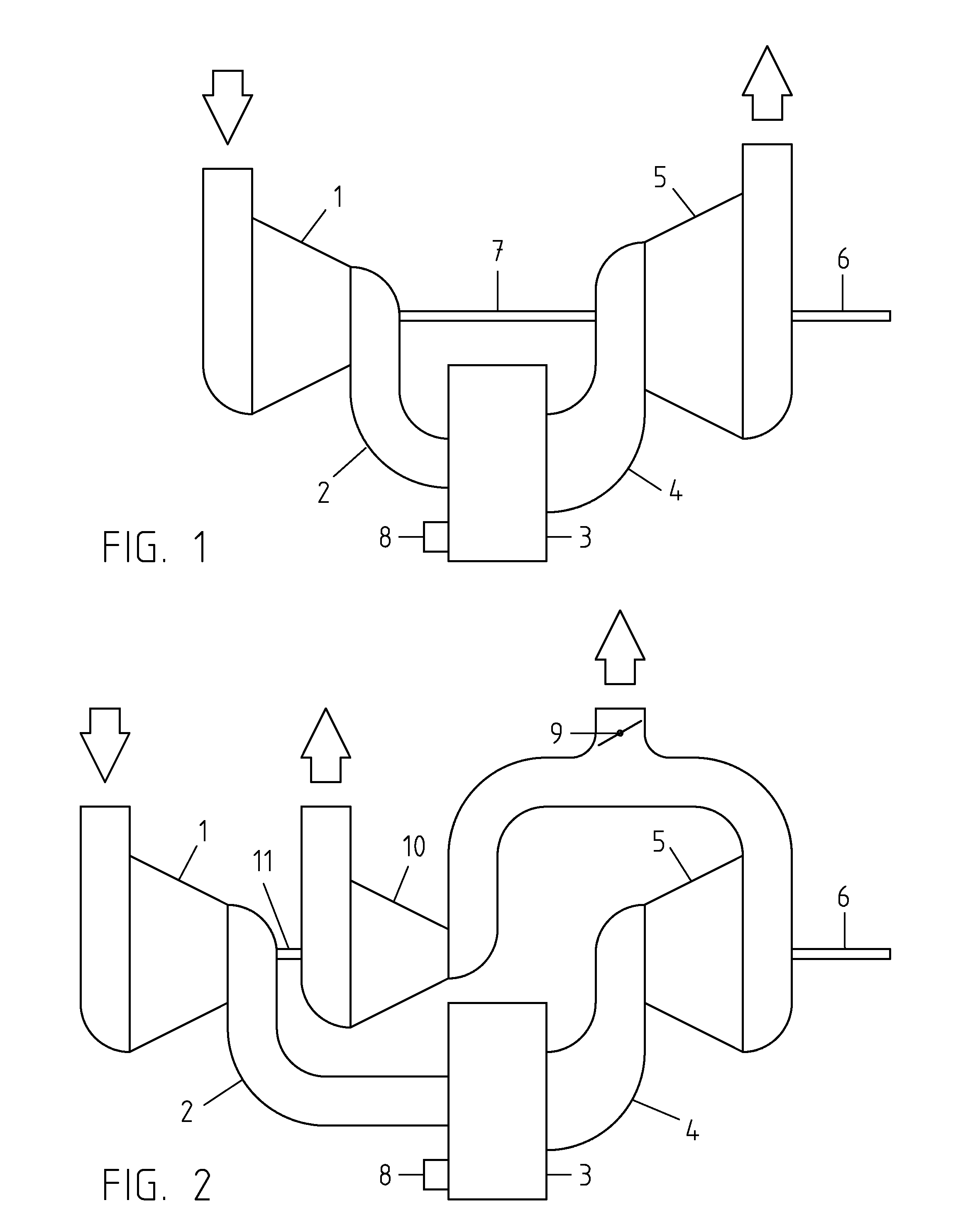
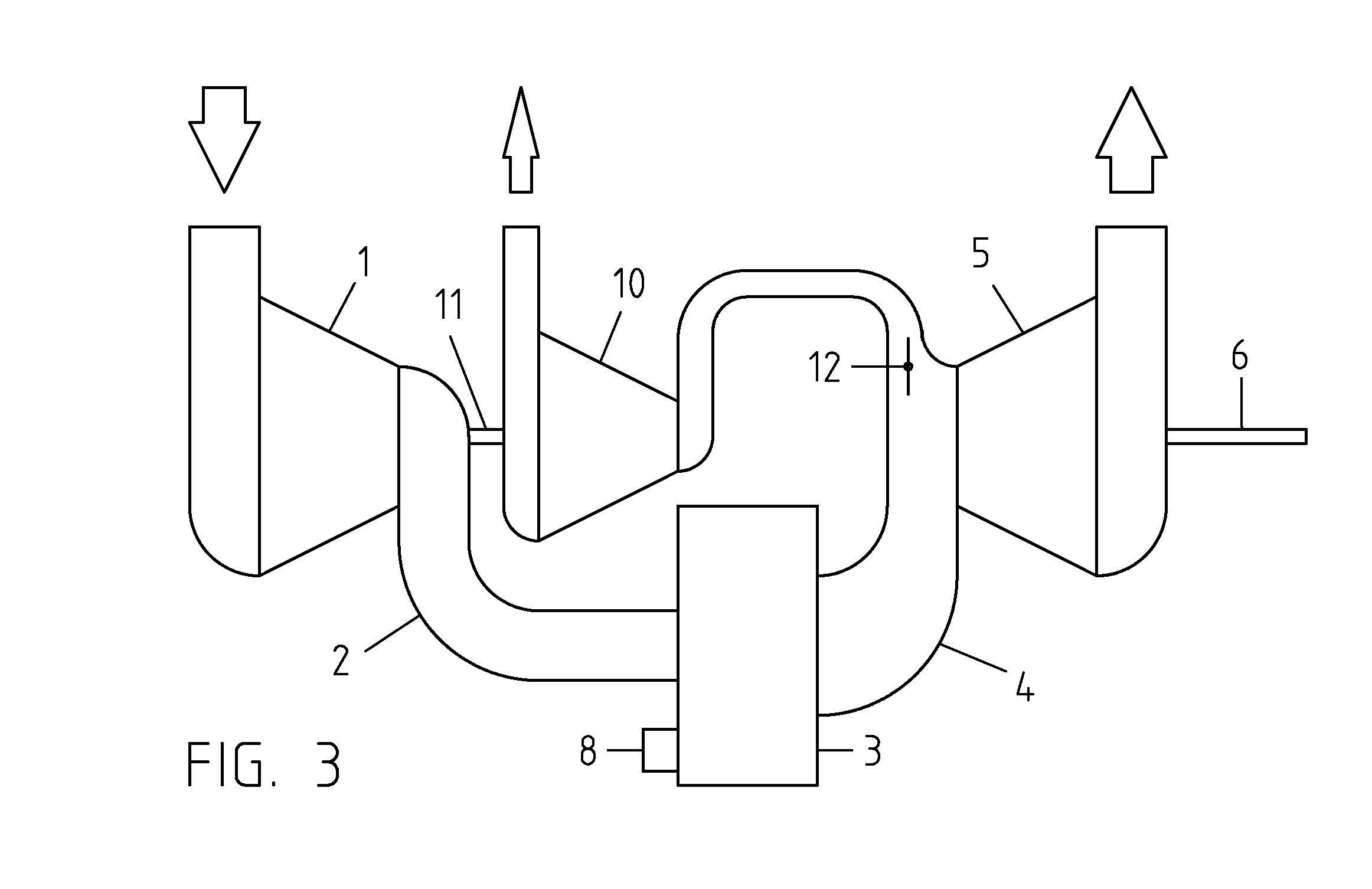
[0032]FIG. 1 shows one possible arrangement that might be compared to a supercharged piston engine where the crank and connecting-rod assembly has been replaced by an aerodynamic power turbine or positive-displacement air motor. Intake air (represented by the downward-pointing arrow) may be compressed in precompressor element 1, which may be an aerodynamic or positive-displacement unit, depending on the application. Precompressor 1, if used, is a high-volume, low-pressure device compared to the oscillating piston in the free-piston component of the engine, which may have a compression ratio of much greater than 20:1, depending on operating conditions. Intake duct work 2 conducts the pre-compressed air to the intake ports of the free-piston gas generator 3. The high-temperature, high-pressure gas from gas generator 3 is conducted by exhaust duct work 4 to rotary device 5, which may be an axial or centrifugal turbine, an impulse turbine, or a positive-displacement air motor that may u...


PUM


Abstract

This invention provides a compact, fuel-efficient internal combustion engine that can be used to provide rotating shaft output power to a wide variety of mobile and stationary applications. It is based on a two-stroke free-piston gas generator that implements the homogeneous charge compression ignition (HCCI) combustion principle for essentially constant-volume combustion, and it employs a variable piston stroke to maintain a high level of efficiency across a wide range of loads and speeds. A rotary device, which may be of either an aerodynamic or positive displacement type, converts the energetic gas stream to power at a rotating shaft.

Description

CROSS-REFERENCE TO RELATED APPLICATIONS[0001]Not ApplicableSTATEMENT REGARDING FEDERALLY SPONSORED RESEARCH OR DEVELOPMENT[0002]Not ApplicableREFERENCE TO A SEQUENCE LISTING, A TABLE, OR A COMPUTER PROGRAM, LISTING COMPACT DISC APPENDIX[0003]Not ApplicableBACKGROUND OF THE INVENTION[0004]This invention pertains to thermodynamically efficient internal combustion engines, particularly U.S. Patent Classifications 123 / 46R (free piston engines), 123 / 46A (free piston engines with two chambers and one piston), 123 / 46B (free piston engines-phasing means between two or more units) and 60 / 595 (power plants in which a free piston device supplies motive fluid to a motor). In addition to the field of free-piston engines, the invention is relevant to internal combustion engines employing homogeneous charge compression ignition (HCCI). It is also relevant to the efficient operation of internal combustion gas turbine engines. In one embodiment employing compressed air starting, the invention pertai...

Claims


Application Information

Patent Timeline
IPC IPC(8): F02B71/06
CPCF02B1/12F02B25/08F02B2075/025F02B37/00F02B71/00F02B33/38
Inventor SCHWIESOW, PAUL A.SCHWIESOW, RONALD L.TOMASSETTI, JR., DINO
Owner SCHWIESOW PAUL ALBERT
Why Eureka
Try Eureka