Cabin System

a cabin and frame technology, applied in the field of cabin systems, can solve the problems of reduced strength of the support pillar, increased difficulty in inspection operation, and increased cost of operation, so as to reduce the area of obstruction, reduce the total height and the size of the cabin frame, and reduce the effect of work cos

Active Publication Date: 2011-10-06
KUBOTA LTD
View PDF16 Cites 18 Cited by
  • Summary
  • Abstract
  • Description
  • Claims
  • Application Information

AI Technical Summary

Benefits of technology

[0032]With the above-described arrangements, the shape of the front upper beam as the cabin framework is viewed from its front face, can be an arch shape, so that the forward upper field of vision for the driver can be increased. In doing this, there is no need to upwardly extend the pair of right/left front support pillars, disadvantageous increase of the total height and the size of the cabin framework can be avoided. Further, since the above arrangement is possible by a simple work of forming the front upper beam into the forwardly convex arch (i.e. a two-dimensional work), the work cost can be restricted low. Further, if the front upper beam is comprised of an angular pipe having a quadrilateral cross section and a bottom face of the front upper beam is set substantially parallel with the line of sight of the driver seated a the driver's seat inside the cabin framework, the front upper beam is disposed along the direction parallel with the line of sight of the driver when this driver views the f...

Problems solved by technology

However, this can not only lead to disadvantage of reduced strength of the support pillar, but can impose limitation on the cross sectional area of the support pillar, which limitation makes it impossible to secure an aperture area greater than the cross sectional area of the support pillar required as a duct aperture area (air passageway cross...

Method used


Image

  • Cabin System
  • Cabin System
  • Cabin System

Examples


Embodiment Construction

)

[0075]Next, embodiments of a cabin system according to the present invention will be described.

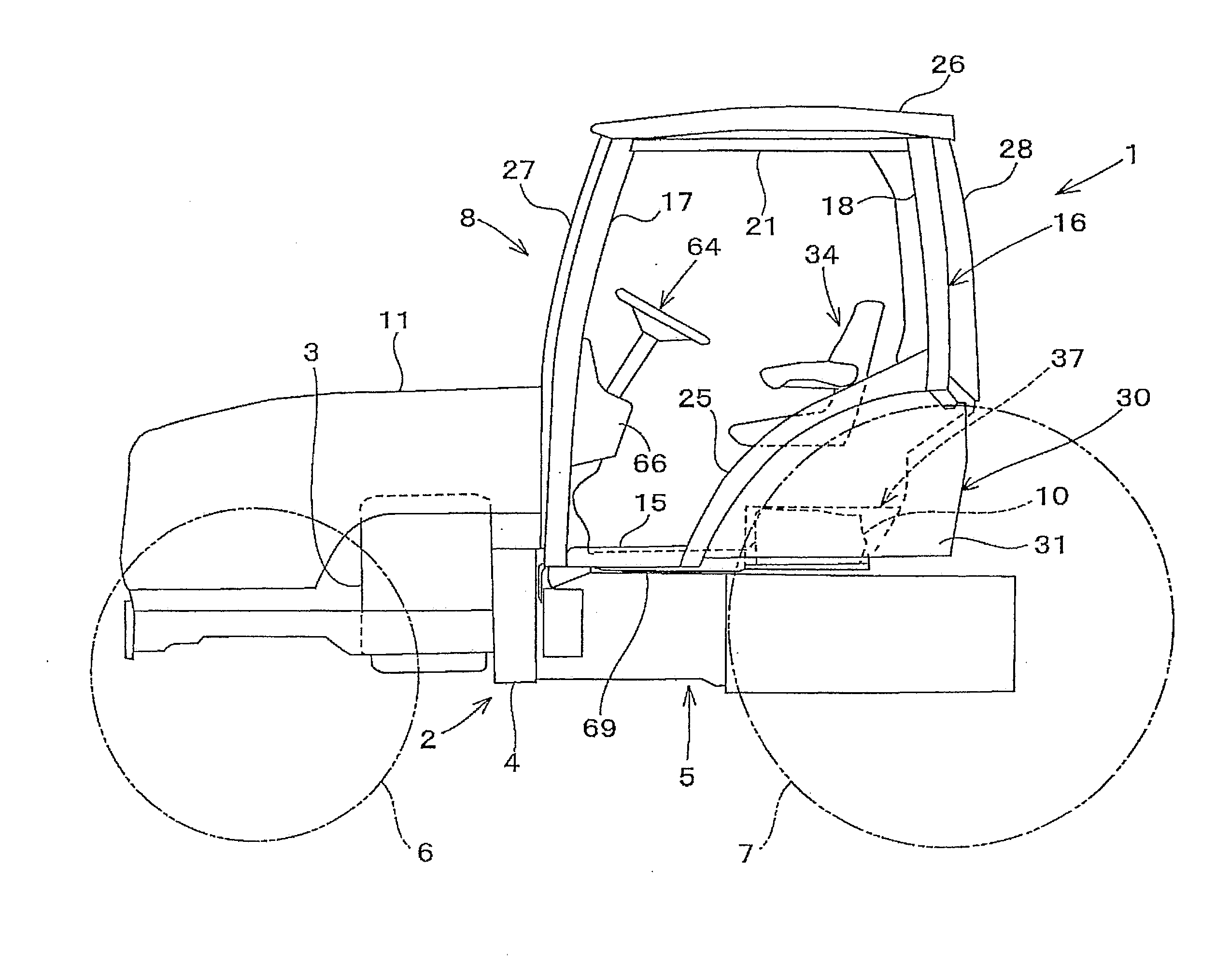
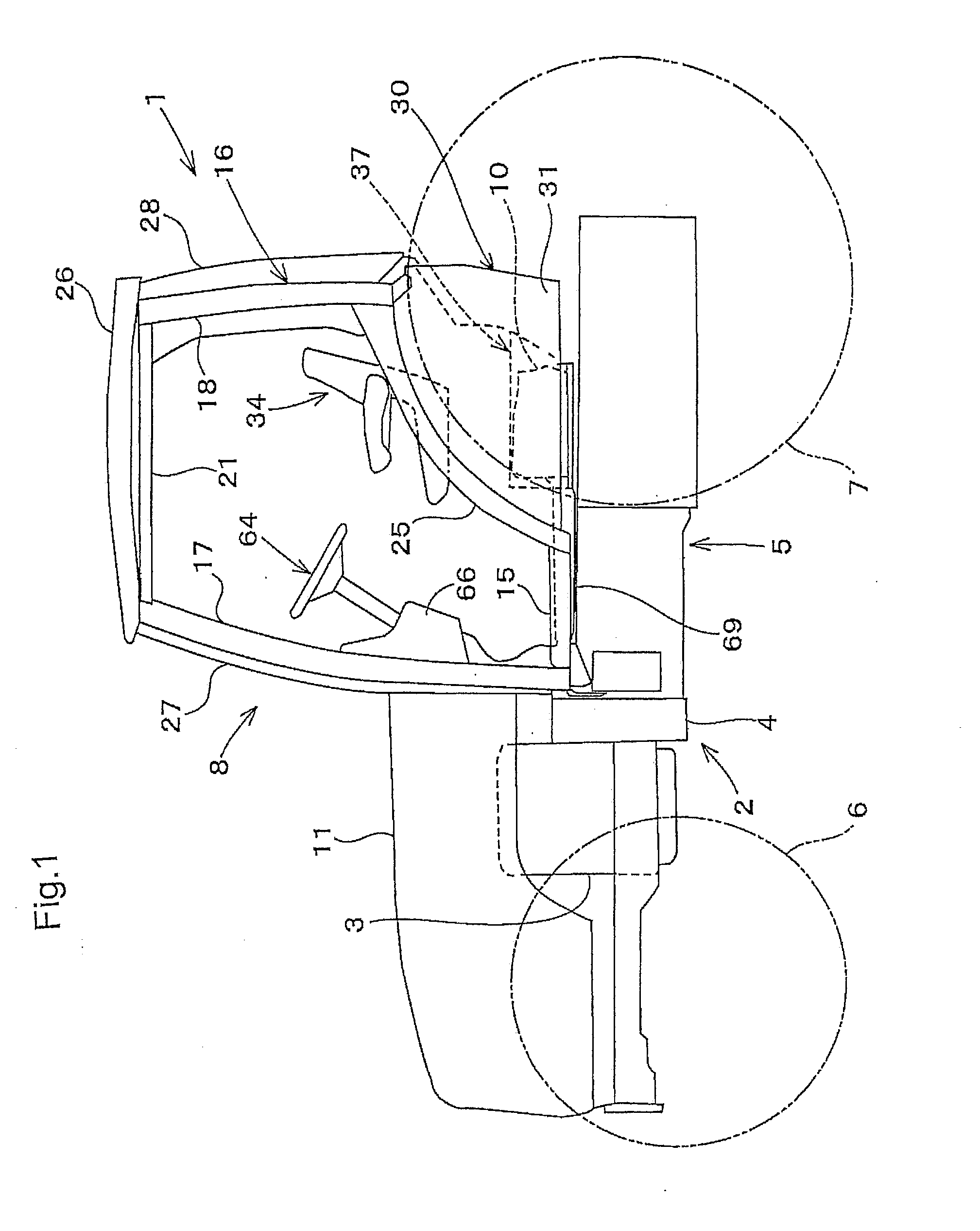
[0076]FIG. 1 shows a tractor 1 employing this cabin system. A vehicle body 2 of this tractor 1 is an interconnected structure of a transmission case 5 disposed rearwardly of an engine 3, comprised of a flywheel housing 4, a clutch housing and a transmission case, etc. This vehicle body 2 is supported on right / left pairs of front and rear wheels 6, 7 to be capable of traveling. A cabin 8 is mounted on a rear portion of this vehicle body 2.

[0077]This tractor 1 mounts an air conditioning unit (“an air conditioner”) for performing conditioning of air present inside the cabin 8. The air conditioning unit includes a cooling unit and a heating unit.

[0078]The cooling unit includes e.g. a compressor for compressing cooling medium, a condenser (heat discharger) for condensing / liquefying compressed cooling medium from the compressor while discharging heat therefrom, an expansion valve for depressuri...


PUM


Abstract

A cabin system to be mounted on a vehicle body is disclosed. The cabin system includes a driver's seat, an air conditioner body for indoor air conditioning disposed downwardly of the drive's seat, a plurality of support pillars constituting a cabin framework, a ceiling portion, and a main duct having a hollow tubular construction, the main duct forming therein an air passageway for the indoor air conditioning. The main duct includes, at a lower portion thereof, a duct connecting opening to be connected to the air conditioner body and also includes, at a lateral portion thereof, a support pillar engaging face. The main duct is attached through the support pillar engaging face to one of the support pillars along an indoor side peripheral face of the one support pillar. The support pillar engaging face of the main duct and the indoor side peripheral face of the one support pillar have profiles complementary with each other.

Description

FIELD OF THE INVENTION[0001]The present inventions relates to a cabin system to be mounted on a vehicle such as a tractor.DESCRIPTION OF THE RELATED ART[0002]A cabin to be mounted on a vehicle body such as that of a tractor includes an air conditioner for making the cabin indoor environment comfortable. The body of the air conditioner having such air conditioner components as an evaporator, a blower, etc. can be disposed under a driver's seat inside the cabin. In this, in order to allow introduction of ambient air into the air conditioner body through an ambient air introducing opening provided in a ceiling portion of the cabin, an arrangement is known from the JP 2006-008075 A (or U.S. Pat. No. 7,290,829 B2 corresponding thereto), in which by utilizing the hollow structure of a support pillar of the cabin, this support pillar is utilized also as an ambient air introducing duct. For permitting such utilization of the cabin support pillar as an ambient air introducing duct as known f...

Claims


Application Information

Patent Timeline
IPC IPC(8): B62D33/06
CPCB60H1/00378B60H2001/00221B60H2001/00228B62D33/0617B62D33/06B62D25/07E02F9/166B62D33/0604B62D33/067E02F9/163E02F9/0833E02F9/0858B62D25/2036
Inventor OBE, MITSUHIKOHIRANO, AZUSAISHIDA, EIICHIISHIDO, KENICHI
Owner KUBOTA LTD
Why Eureka
Try Eureka