Abrasive slurry formulations containing NANO and micro spheres additives or self-assembled monolayers

Inactive Publication Date: 2011-10-06
SCHWAPPACH KARL
View PDF0 Cites 12 Cited by
  • Summary
  • Abstract
  • Description
  • Claims
  • Application Information

AI Technical Summary

Benefits of technology

[0008]The present invention improves the embedded abrasive height distribution in lapping plates. The height distribution of diamonds improves the surface finish and reduces the

Problems solved by technology

Protruding abrasives from the mean height distribution of the diamonds produce scratches in the polishing surface.
A typical example of magnetic slider bars with trailing edges composed of metallic l

Method used


Image

  • Abrasive slurry formulations containing NANO and micro spheres additives or self-assembled monolayers
  • Abrasive slurry formulations containing NANO and micro spheres additives or self-assembled monolayers
  • Abrasive slurry formulations containing NANO and micro spheres additives or self-assembled monolayers

Examples


Example

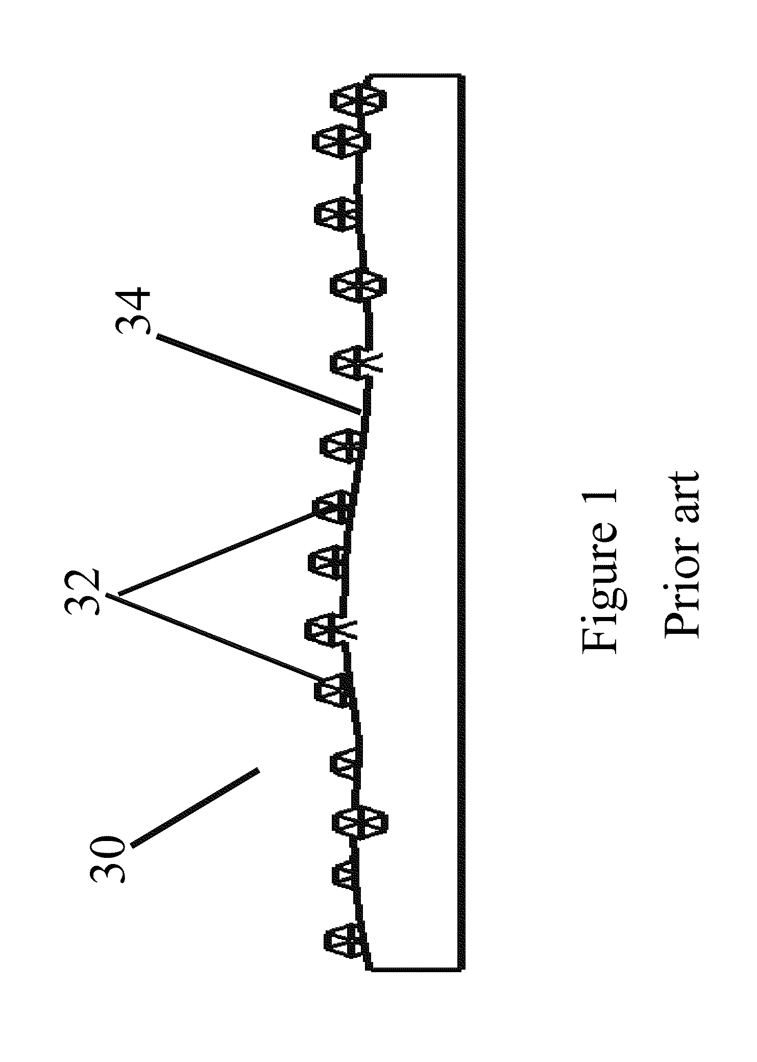
[0023]FIG. 1 depicts a prior schematic representation of a charged lapping plate 30 with diamonds 32 on a soft substrate 34. The non uniform height distribution of the diamonds cause a relatively rough finish with scratches experienced by the lapped surface. The high protruding diamonds cause tensile stresses at the surface of ceramic materials. Tensile stresses further cause particle release which is undesirable in many applications.

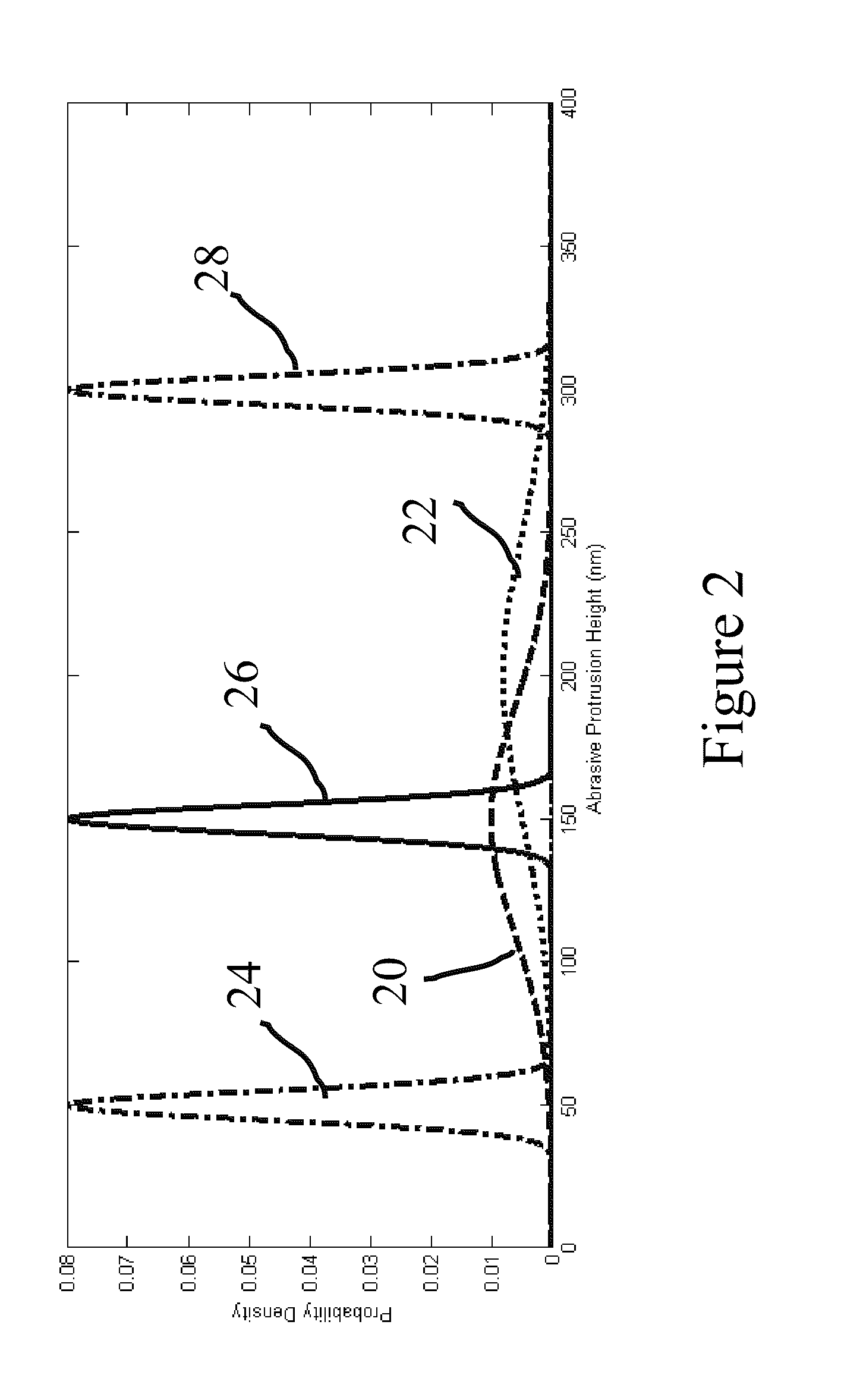
[0024]FIG. 2 reflects prior art abrasive height distribution 22 and 20 versus distributions 24, 26, and 28 obtained with the present invention. In prior art applications; large variations are obtained in diamond height distributions as depicted by 22 and 20. Also mean shift from batch to batch charging operations cause mean variations as depicted by 20 and 22. The present invention can precisely dial in a diamond height such as the examples shown in 24, 26, and 28 by precisely controlling the nanospheres diameters into the slurry. For example adding nan...


PUM


Abstract

This invention relates to methods for plate dressing using slurry charged with abrasives and soft polymeric or metallic micro-nano spheres additives to produce substantially uniform abrasive height. Additionally, methods for plate dressing using slurry charged with abrasives and self-assembled polymers to produce substantially uniform abrasive height are disclosed.

Description

CROSS-REFERENCE TO RELATED APPLICATIONS[0001]This application claims the benefits of the filing date of U.S. Provisional Patent Application Ser. No. 61 / 320,787, which is entitled “Lapping slurry formulations containing nanospheres additives” filed Apr. 5, 2010, which is hereby incorporated herein in their entirety by reference.BACKGROUND[0002]Lapping is a well-known process of abrasion metal-removal or machining for smoothing or polishing surfaces to a high degree of refinement or accuracy using loose abrasive lapping compound embedded in soft plate referred to as lapping plates. The lapping compound is often in a liquid suspension or semi-liquid form, and is called lapping slurry.[0003]Polishing quality produced on a lapping plate is a strong function of the abrasive height distribution and abrasive density. The tighter the height distribution one can achieve the smoother the finish of the final polishing surfaces. Protruding abrasives from the mean height distribution of the diamo...

Claims


Application Information

Patent Timeline
IPC IPC(8): B24B41/00C09K3/14
CPCC09K3/1454C09K3/1409
Inventor BOUTAGHOU, ZINE-EDDINE
Owner SCHWAPPACH KARL
Why Eureka
Try Eureka