
Lightweight unit load device

a technology of light weight and load device, applied in the field of polymer composite materials, can solve the problems of not providing significant weight savings, and achieve the effects of low cost, high strength ratio, and low weigh

Inactive Publication Date: 2011-10-13
COMPOSITE TRANSPORT TECH
View PDF25 Cites 62 Cited by
  • Summary
  • Abstract
  • Description
  • Claims
  • Application Information

AI Technical Summary

Benefits of technology

[0009]The demands of each component part of the container were evaluated and materials were selected and in multiple cases created to address the specific needs of the component part. In addition, the physical requirements each part was created to have a low weight to high strength ratio and low cost.
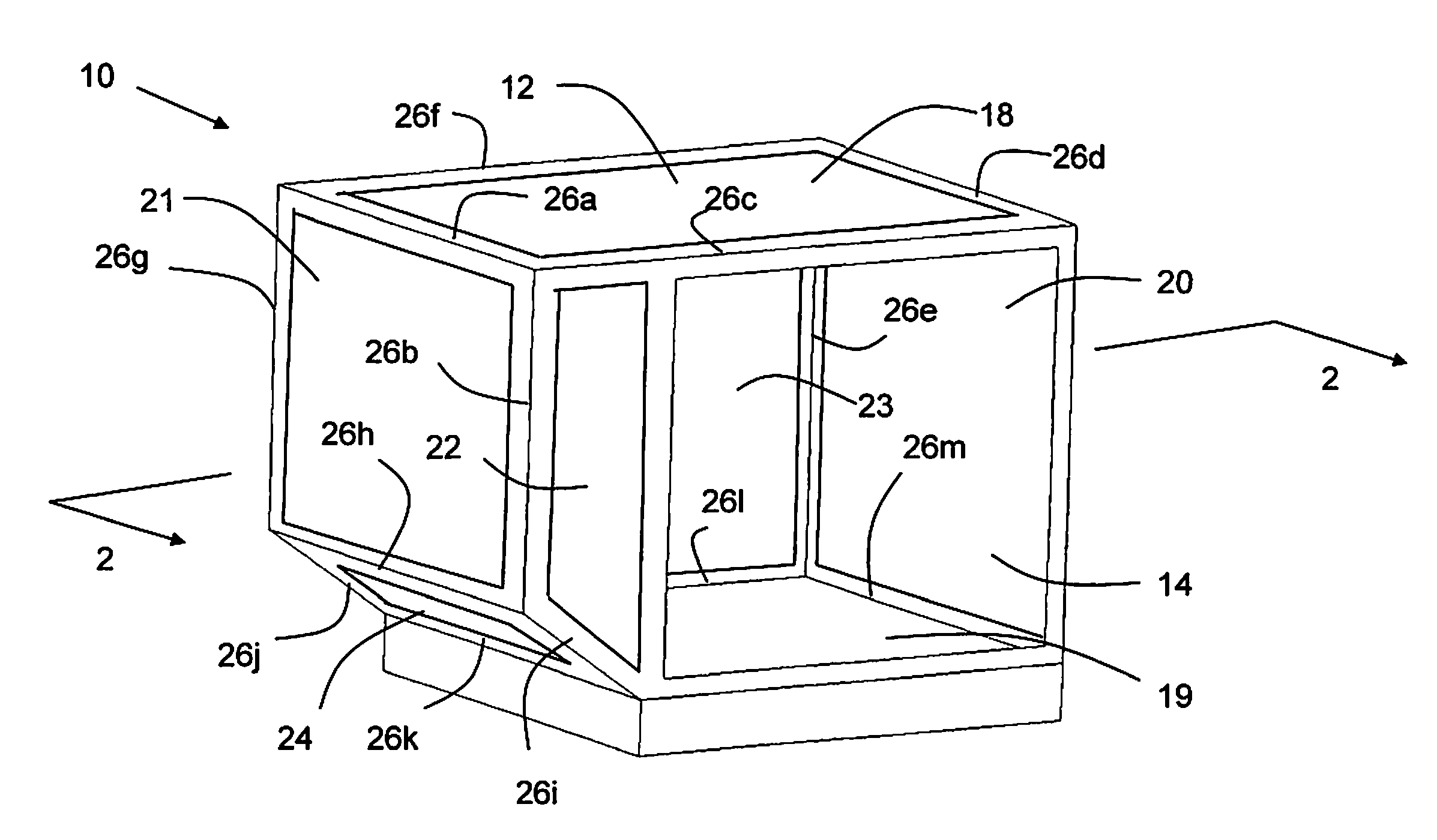
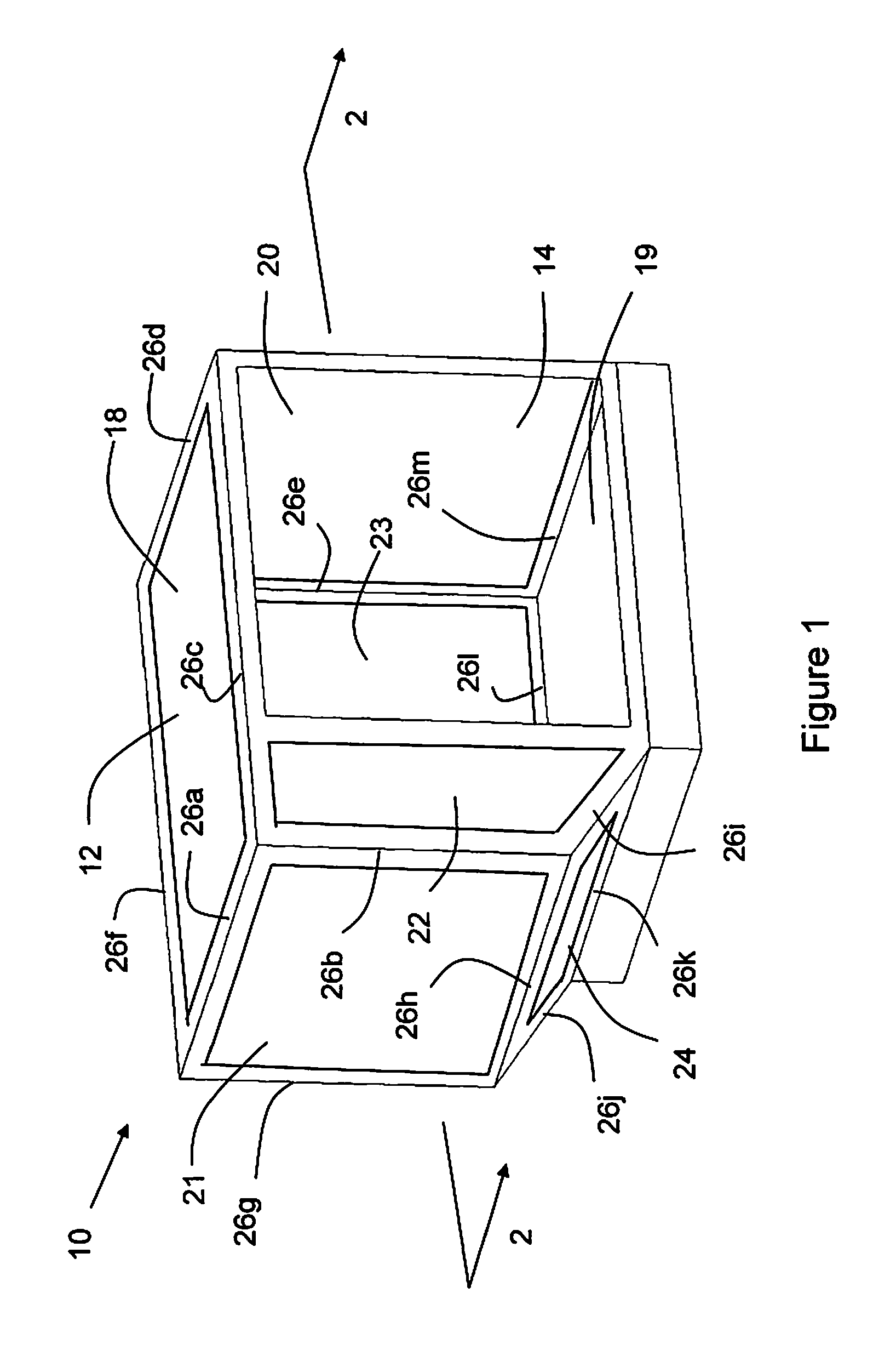
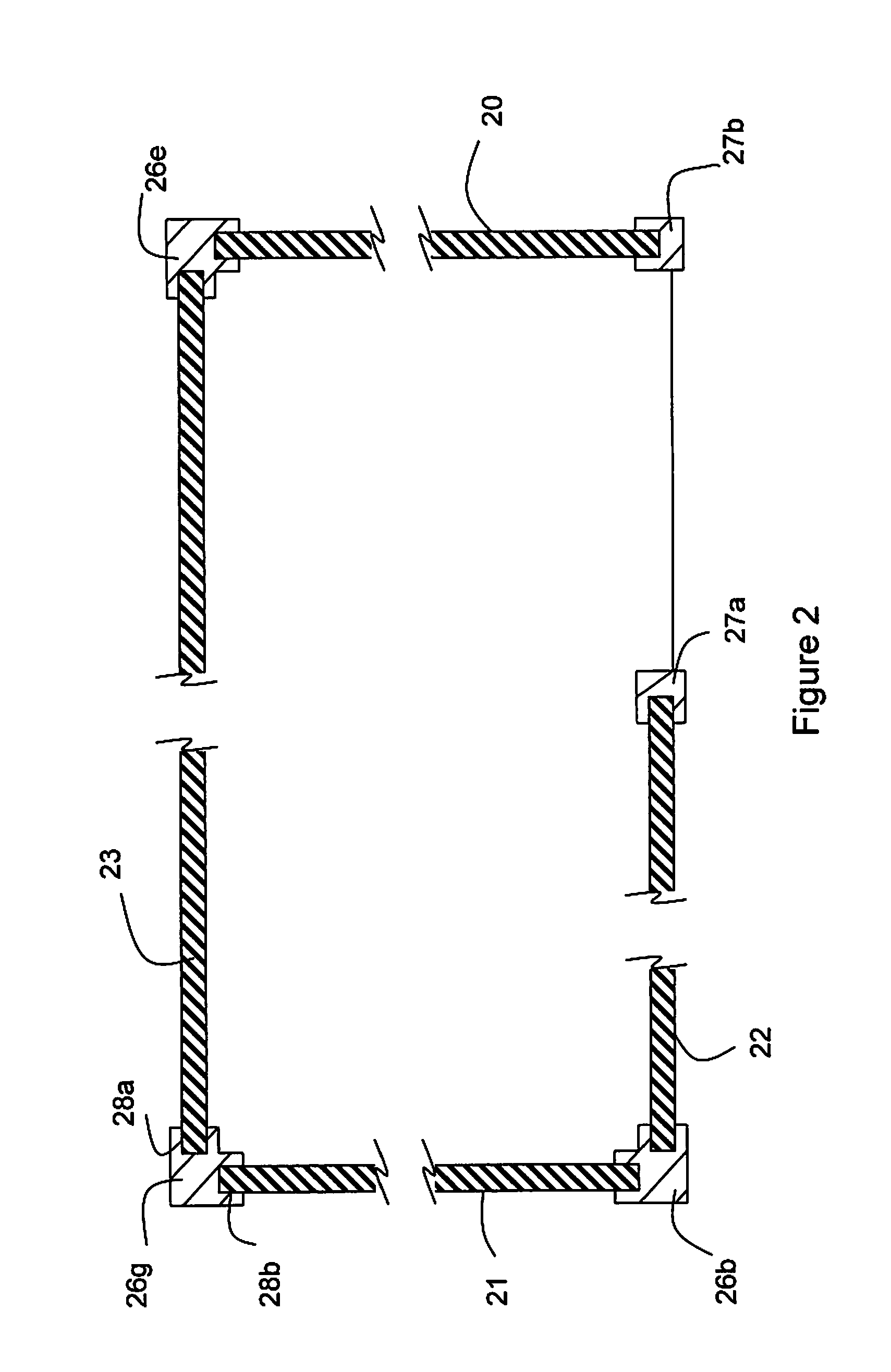
[0010]The techniques described herein can provide advantageous cost savings, amongst the various advantages possible. For example, the techniques and materials used to provide the corner joints from carbon fibers and resin can be used to produce light weight, high strength materials suitable for numerous applications. For example, as is understood in the transport industries, such as cargo transport, people transport (e.g., passenger airlines, trains, buses, cars, ships) and motor vehicles generally, a reduction in weight typically results in a reduction in fuel consumption, which will provide costs savings. Cost savings will be advantageous to the owner or operator of the cargo transport service, people transport service or motor vehicle. Some embodiments include a container comprising a plurality of polymer composite wall panels connected together by a plurality of polymer composite joints and defining at least a partially enclosed volume, wherein the plurality of polymer composite wall panels comprise a core of a first polymer composite material and a polymer composite surface layer of a second polymer composite material bonded to opposing surfaces of the core, and wherein the second polymer composite material exhibits an elastic modulus lower than that for the first polymer composite material. The container may include a first polymer composite material selected from the group consisting of a carbon fiber reinforced composite material and a glass fiber reinforced composite material. The container may include a second polymer composite material that is a polymer fiber reinforced composite material having reinforcing fibers selected from the group consisting of polyethylene, polypropylene, aramid, TEGRIS, and KEVLAR. In some embodiments, the container may exhibit a weight to volume ratio ranging from about 0.6 lbs / ft3 to about 0.8 lbs / ft3. In further embodiments, the container may include an aircraft cargo LD-3 container and exhibit a ratio of container tare weight to FAA certification load of 0.02 to about 0.03 relative to the IATA, 23rd Edition, Effective Jul. 1, 2008. In some embodiments, polymer composite wall panel of the container may exhibit weight ranging from about 0.1 to about 0.2 lbs / ft2. Further, in additional embodiments, the container may include polymer composite joints comprising a fiber reinforced composite material having reinforcing fibers selected from the group consisting of carbon fibers. aramid fibers, KEVLAR, and glass fibers. The composite joints may comprise carbon fiber reinforce composite material, and wherein the composite joint exhibits a fiber volume fraction ranging from about 60% to about 70%.

Problems solved by technology

The side effect of these containers is that they typically do not provide any significant weight savings over their aluminum ULD counterparts.

Method used


Image

  • Lightweight unit load device
  • Lightweight unit load device
  • Lightweight unit load device

Examples


examples

[0072]Sheets and more complex shapes were pultruded using Zoltek's Panex 35 50 k continuous tow carbon fibers. The carbon fibers had been previously coated with the Hydrosize's U6-01 a sizing. The sizing as previously described was selected to improve fiber wet-out, protect the fibers and improve fiber handling, reduce fuzzing, upon further application of the sizing lubricity was improved by decreasing friction during handling, material properties were also improved. It is anticipated that other urethane-based sizings may be suitable upon some amount of experimentation. The resin selected for applying during the pultrusion process is a polyurethane resin, Baydur PUL 2500. The carbon fibers were pulled from multiple spools to provide strands or bundles of carbon fibers which were fed through a sheet / panel / creel card with multiple openings to keep the various strands oriented and separated from each other improve handling of the carbon fibers and assist in wet-out. Then the fibers pro...


PUM

PropertyMeasurementUnit
volume fractionaaaaaaaaaa
temperatureaaaaaaaaaa

Abstract

A unit load device constructed from fiber reinforced polymer matrix composite materials is described. Individual panels of the unit load device may be customized with composite materials and patterns. The joints are adapted to receive the ends of the panels of the unit load device and may further be customized with fiber reinforced composite materials to strengthen the joint. Some embodiments provide for construction of a unit load device from a variety of fiber reinforcing materials utilizing a matrix of thermoplastic polymers with similar softening temperatures. Each component part within the container was designed and / or created to address the specific needs of the particular part. The unit load devices described herein provide for all composite containers with a significant weight savings from conventional unit load devices.

Description

FIELD OF THE INVENTION[0001]The present invention pertains to polymer composite materials useful for a variety of purposes, such as, for example, containers or load carrying containers. More particularly, the present invention pertains polymer composite materials that exhibit high strength to weight ratios that can be used to construct, for example, load carrying containers which are lightweight or other objects with walls that are high strength and light weight.BACKGROUND OF THE INVENTION[0002]Within the airline industry it is a standard practice to compartmentalize the cargo which is to be carried on board the larger aircraft. This is done by separating the cargo into separate units and placing these units of cargo into individual containers which are commonly referred to as unit load devices (ULDs). Because of regulatory requirements, as well as practical considerations, the shape, size and maximum weight of a ULD for each type aircraft has been largely standardized.[0003]Typical...

Claims


Application Information

Patent Timeline
Patent Type & Authority Applications(United States)
IPC IPC(8): B65D90/00B29C70/52B32B7/02B32B7/022
CPCB29C70/521Y10T428/24942B29L2031/7126B32B5/26B32B7/02B32B2262/02B32B2262/101B32B2262/106B32B2307/51B65D88/14B65D90/022B65D90/08B29C66/12441B29C66/4326B29C66/7212B29K2875/00B29K2307/04B29C66/72143B29C66/7392B29C66/72141B29C66/71B29C66/7394B32B5/02B32B5/22B32B27/18B32B2250/20B32B2250/42B32B2260/021B32B2260/046B32B2262/0253B32B2262/0269B32B2307/3065B32B2307/308B32B2307/546B32B2307/558B32B2307/714B32B2307/718B32B2439/62B32B2605/18B29C65/18B32B7/022B29K2023/10B29K2075/00B29K2071/00B29K2067/00B29K2081/04B29K2063/00B29K2309/08B29K2277/10B29K2077/10B29K2027/18B29K2023/12B29K2023/0683B29K2023/06
Inventor LUCAS, RICKMERRIMAN, DOUGLASMCDONOUGH, SAUNDRATWEDDLE, ALLAN
Owner COMPOSITE TRANSPORT TECH
Learn More