Lighting device and display device

a technology of light source and display device, which is applied in the direction of lighting and heating apparatus, planar/plate-like light guides, instruments, etc., can solve the problems of increasing the long wavelength component of illumination light, and achieve the effects of reducing the variation of light intensity distribution of illumination light, high transparency, and increasing distan

Active Publication Date: 2011-10-13
SONY CORP +1
View PDF13 Cites 34 Cited by
  • Summary
  • Abstract
  • Description
  • Claims
  • Application Information

AI Technical Summary

Benefits of technology

[0032]When the first region in the light modulation element mainly includes a liquid crystal material, and the second region in the light modulation element mainly includes a polymer material, a combination of the liquid crystal material and the polymer material is appropriately selected, thereby refractive-index difference Δ(neL−nop) or Δ(nep−noL), which determines a scattering property, may be adjusted to be small in a short wavelength side and large in a long wavelength side (reverse wavelength dispersion of refractive index). Wavelength dependence of scattering is adjusted in this way, thereby in-plane variation of light intensity distribution of illumination light may be reduced over the whole visible range.
[0033]The amount of long-wavelength light increases with increase in distance from a light source due to absorption of the ITO film. The amount of short-wavelength light increases in a region near the light source due to a scattering characteristic of the light modulation element. However, while the amount of short-wavelength light increases in the light guide plate due to reflection of the ITO film, long-wavelength light, which has not been reflected, enters the light modulation element. This increases the amount of long-wavelength light in light scattered in the light modulation element. When a distance from the light source further increases, long-wavelength light is consumed by scattering, and therefore the amount of short-wavelength light gradually increases in light outputted from the light guide plate. As a result, short-wavelength light, long-wavelength light and short-wavelength light are arranged in order from a light source side. Thus, one or more of the above measures is used, so that in-plane variation of light intensity dist

Problems solved by technology

However, the backlight has a difficulty, namely, a long wavelength component of illumination light

Method used


Image

  • Lighting device and display device
  • Lighting device and display device
  • Lighting device and display device

Examples


first embodiment

1. First Embodiment

Example of Using Horizontal Alignment PDLC

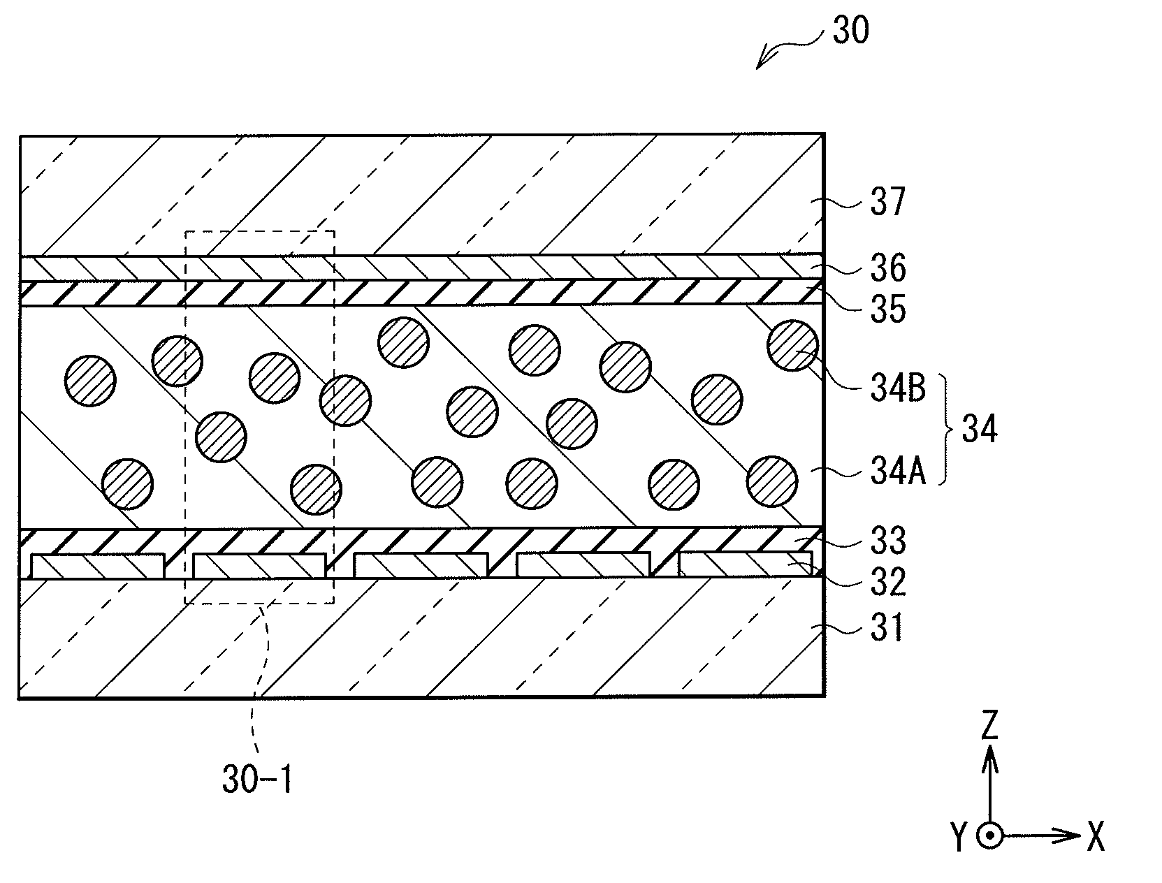
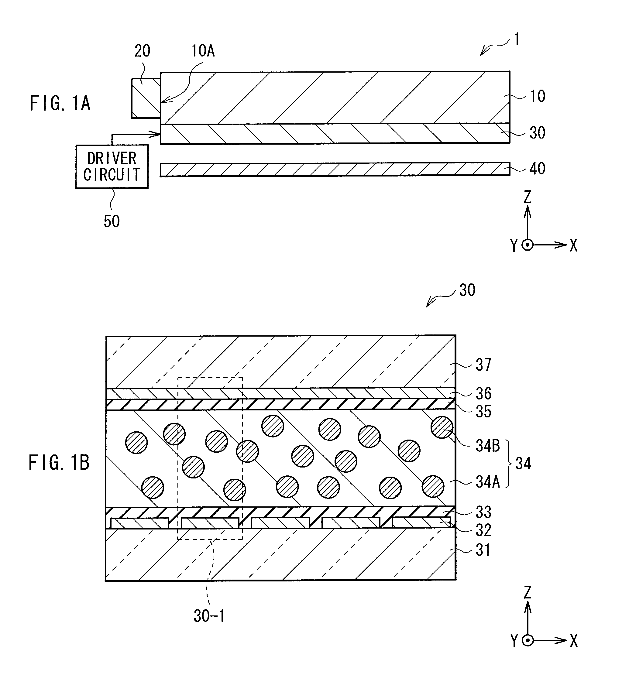
[0072]FIG. 1A shows an example of a sectional configuration of a backlight 1 according to a first embodiment of the invention. FIG. 1B shows an example of a sectional configuration of a light modulation element 30 in the backlight 1 of FIG. 1A. FIGS. 1A and 1B are schematic diagrams and therefore dimensions or shapes are not necessarily the same as actual ones. For example, the backlight 1 lights a liquid crystal display panel from the back, and includes a light guide plate 10, a light source 20 disposed on a side face of the light guide plate 10, a light modulation element 30 and a reflective plate 40 disposed behind the light guide plate 10, and a driver circuit 50 driving the light modulation element 30.

[0073]The light guide plate 10 guides light from the light source 20, disposed on the side face of the light guide plate 10, to a top of the light guide plate 10. The light guide plate 10 has a shape in correspondence to...

second embodiment

2. Second Embodiment

Example of Using Vertical Alignment PDLC

[0169]Next, a backlight 2 according to a second embodiment is described. FIG. 20A shows an example of a sectional configuration of the backlight 2 according to the embodiment. FIG. 20B shows an example of a sectional configuration of a light modulation element 60 in the backlight 2 of FIG. 20A. The backlight 2 of the embodiment is different from the backlight 1 of the above embodiment in that a vertical alignment film is used for alignment films 33 and 35, and a light modulation layer 64 is provided in place of the light modulation layer 34 in the above embodiment. Hereinafter, points common to the configuration of the above embodiment are appropriately omitted to be described, and points different from the configuration are mainly described.

[0170]As described before, a vertical alignment film is used for the alignment films 33 are 35 in the embodiment. The vertical alignment film is used to form pre-tilt where a bulk 64A a...

examples 1 and 2

[0234]First, a monomer type was adjusted to increase scattering efficiency in order to improve wavelength dependence of scattering. For evaluation, the small glass cell produced by the above-mentioned production method was used, and comparison was made between the example 1, where only a bifunctional monomer was used for the monomer-mixed liquid crystal, and the example 2, where the trifunctional monomer was added by 20 percent by weight of total monomer (FIGS. 27A and 27B). FIG. 27A shows luminance in a white state at a cell thickness of 7 μm and a drive condition of drive voltage of 140 Vpp and applied frequency of 100 Hz. FIG. 27B shows wavelength dependence of scattering in the white state.

[0235]FIG. 27A reveals that the trifunctional monomer is added to the bifunctional monomer, thereby luminance is increased to 6165 cd / m2 to 7552 cd / m2 both inclusive. FIG. 27B reveals that slopes k (nm−1) obtained by linear approximation using the least squares method are −0.00059 and −0.00046...


PUM

PropertyMeasurementUnit
Lengthaaaaaaaaaa
Lengthaaaaaaaaaa
Angleaaaaaaaaaa

Abstract

A lighting device includes: a light guide plate; a light source disposed on a side face of the light guide plate; and a light modulation element disposed on a surface or in the inside of the light guide plate and adhered to the light guide plate. The light modulation element has a pair of transparent substrates disposed separately and oppositely, a pair of electrodes provided on respective surfaces of the pair of transparent substrates, and a light modulation layer provided in a gap between the pair of transparent substrates. The light modulation layer includes a first region, having optical anisotropy, responsive to an electric field, and a second region, having optical anisotropy, unresponsive to an electric field. The second region has a striped structure with average striped texture size of 0.05 μm to 10 μm both inclusive in a short axis direction.

Description

BACKGROUND OF THE INVENTION[0001]1. Field of the Invention[0002]The present invention relates to a lighting device and a display device, each device having a light modulation element exhibiting a scattering property or a transparent property with respect to light.[0003]2. Description of Related Art[0004]Recently, a liquid crystal display has been rapidly improved in image quality or advanced in energy saving, and a method of partially modulating intensity of light from a backlight has been proposed to improve scotopic contrast. In the method, mostly, light emitting diodes (LEDs), used for a light source of a backlight, are partially driven to modulate light from a backlight in accordance with a display image. In addition, size reduction has been increasingly demanded in a large-size liquid crystal display as well as in a small-size liquid crystal display. Therefore, attention is being focused on an edge light type, where a light source is disposed on an edge of a light guide plate, ...

Claims


Application Information

Patent Timeline
IPC IPC(8): G02F1/13357F21V8/00G02F1/01
CPCG02B6/005G02B6/0051G02F1/134336G02F1/1334G02F1/133615G02B6/0055
Inventor UCHIDA, TATSUOISHINABE, TAKAHIROKAWAKAMI, TOHRUSUZUKI, TOMOAKIOKUYAMA, KENTAROEBISUI, AKIRASATO, HARUMIMIZUNO, MAMORUIKEDA, MASAHIROSHINKAI, SHOGO
Owner SONY CORP
Why Eureka
Try Eureka