
Fine silver particle powder, method for manufacturing the same, silver paste using the powder, and method of use of the paste

a silver particle and powder technology, applied in the field of silver particles, can solve the problems of high investment, inability to easily control the nucleation and growth of metal particles, and inconvenient mass production methods, and achieve good low-temperature sinterability

Active Publication Date: 2011-10-20
DOWA ELECTRONICS MATERIALS CO LTD
View PDF4 Cites 24 Cited by
  • Summary
  • Abstract
  • Description
  • Claims
  • Application Information

AI Technical Summary

Benefits of technology

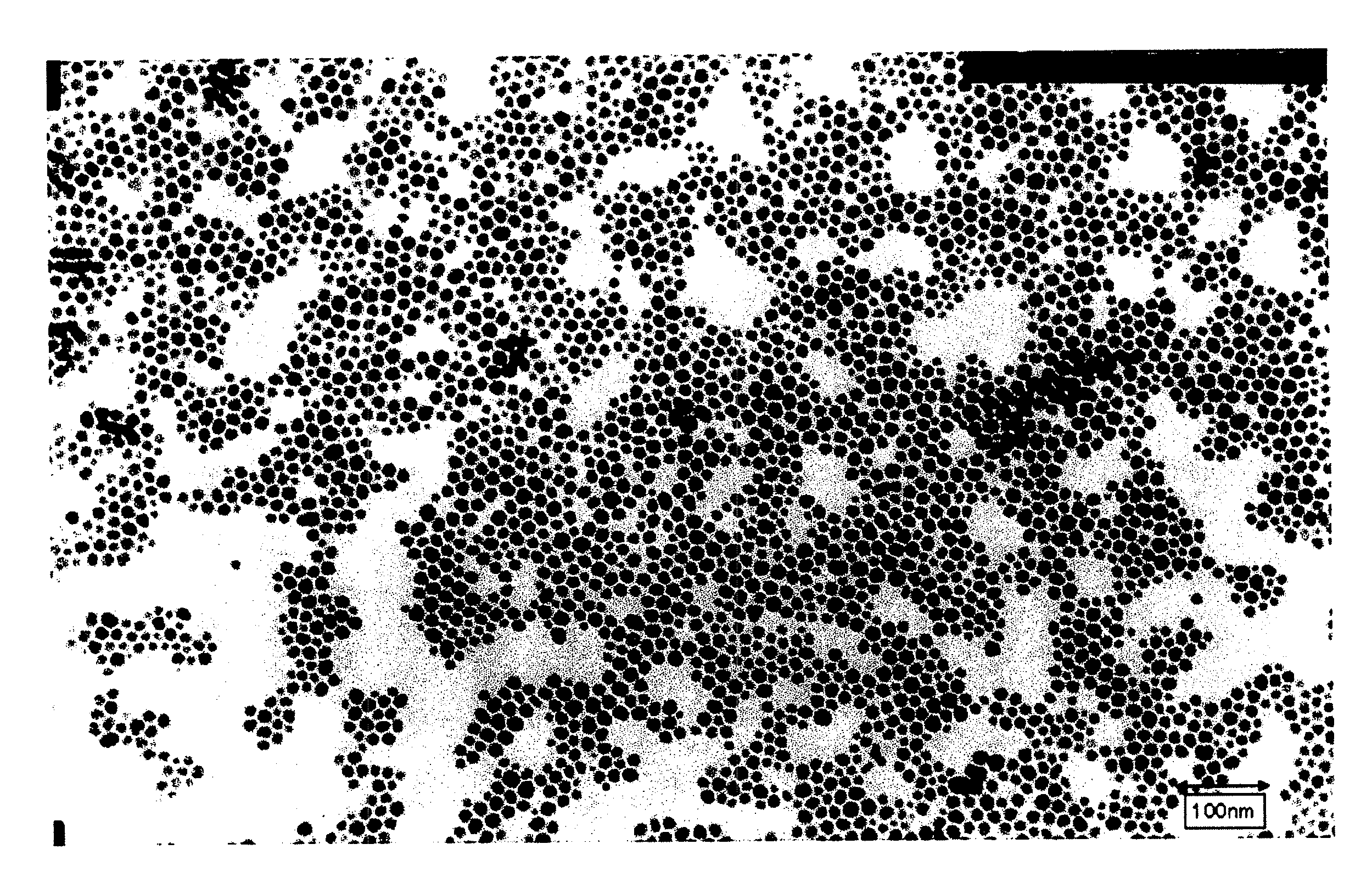
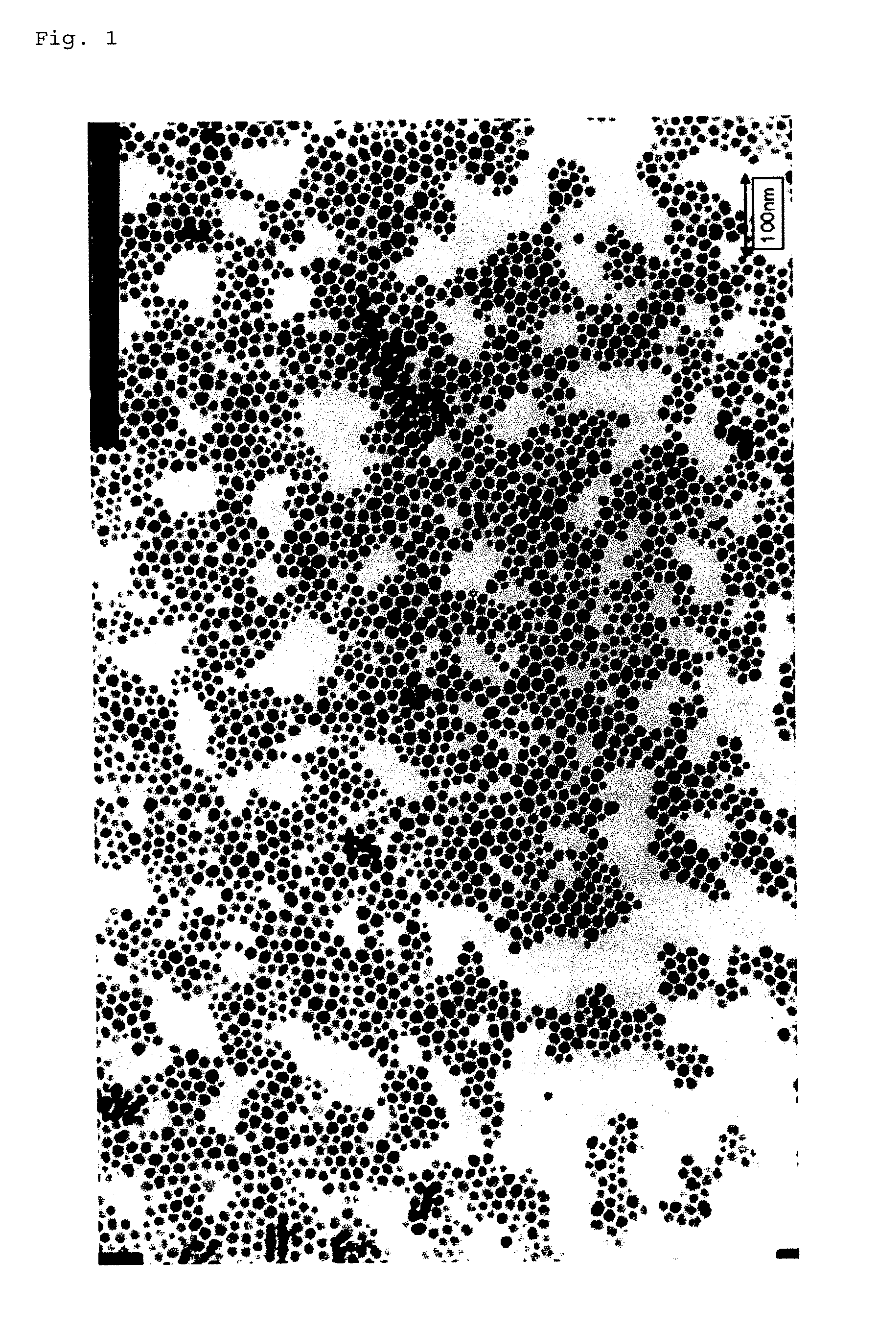
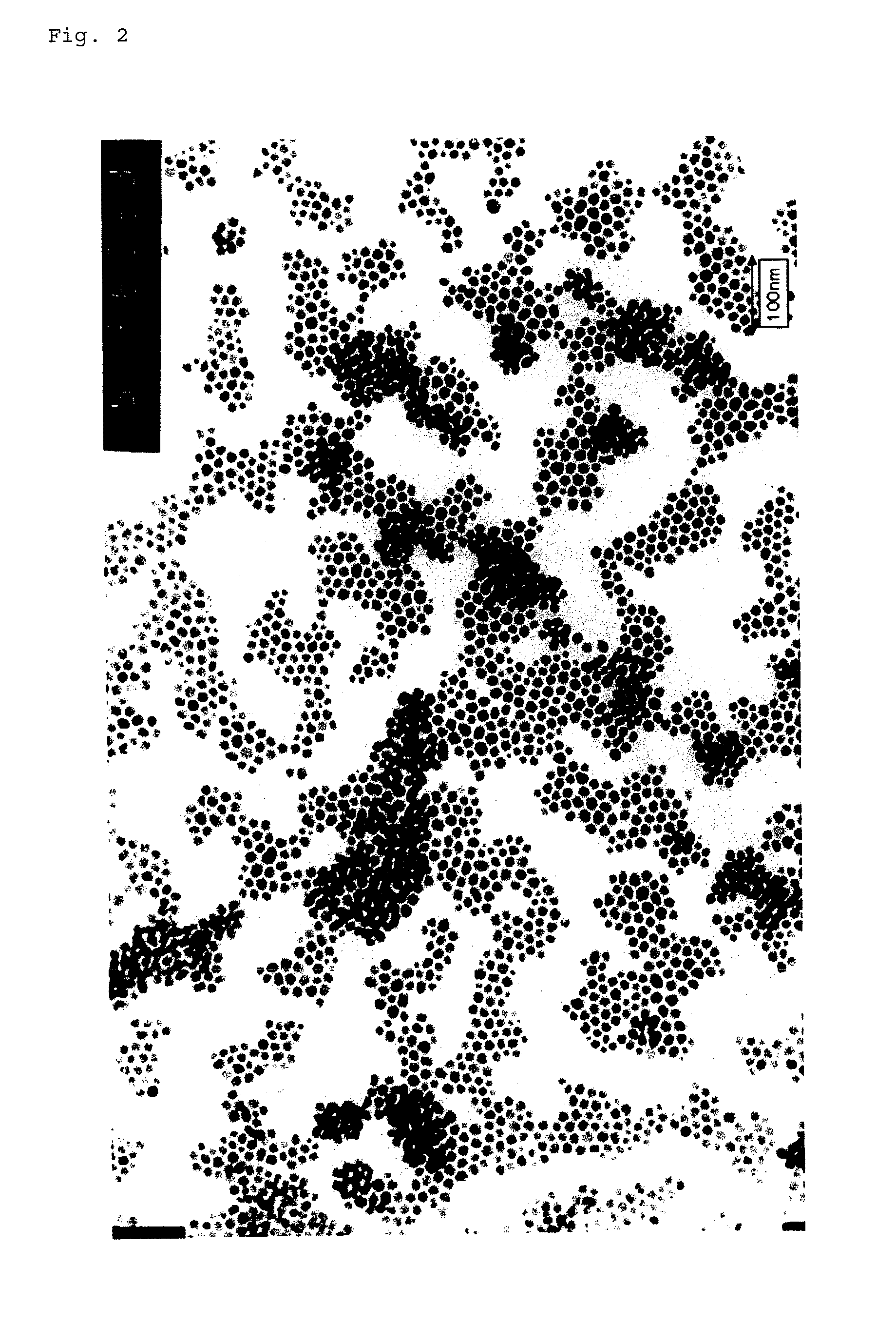
[0023]The use of the methods disclosed in the present description allows a large amount of a fine particle power having an average particle diameter of 5 to 100 nm as measured using a transmission electron microscope to be obtained. In addition, a dispersion and paste having good low-temperature sinterability can be obtained.

Problems solved by technology

Accordingly, the gas phase method has problems in that the initial investment is high and that the method is not suitable for mass production.
Particularly, when nanoparticles are produced by a conventional method in which a reducing agent is added at once to a solution of a metal salt, the nucleation and growth of the metal particles cannot be easily controlled, and therefore it is difficult to obtain particles with a uniform diameter.
However, the use of the surface coating component without any treatment in the environment in which the production reaction proceeds at once as described above causes greater difficulty in obtaining uniformity of the particles.

Method used


Image

  • Fine silver particle powder, method for manufacturing the same, silver paste using the powder, and method of use of the paste
  • Fine silver particle powder, method for manufacturing the same, silver paste using the powder, and method of use of the paste
  • Fine silver particle powder, method for manufacturing the same, silver paste using the powder, and method of use of the paste

Examples


example 1

[0089]A 5 L beaker was used (Examples 1 to 7 and Comparative Examples 1 to 7), and a stirring rod with stirring blades was placed at the center of a reaction vessel. A thermometer for monitoring temperature was placed in the reaction vessel, and a nozzle was also placed in the reaction vessel so that nitrogen could be supplied from its lower part to a solution. An apparatus configured as described above is referred to as a reaction vessel A.

[0090]First, the reaction vessel A was charged with 3,400 g of water, and nitrogen was fed from the lower part of the reaction vessel at a flow rate of 3,000 mL / min for 600 seconds to remove remaining oxygen. Then nitrogen was fed from the upper part of the reaction vessel at a flow rate of 3,000 mL / min to form a nitrogen atmosphere in the reaction vessel. Next, the temperature of the solution in the reaction vessel was adjusted to 60° C. under stirring. Then 7 g of ammonia water containing 28 percent by mass of ammonia was fed to the reaction ve...

examples 2 to 5

[0094]Example 1 was repeated except that the amount of copper added relative to silver was changed to different values. The properties and the like of the particles obtained are shown in Table 1.

examples 6 and 7

[0095]The type of copper was changed, and the amount added was also changed. The reaction apparatus and the reaction flow were unchanged. The properties and the like of the particles obtained are also shown in Table 1.


PUM

PropertyMeasurementUnit
particle diameteraaaaaaaaaa
sublimation pointaaaaaaaaaa
boiling pointaaaaaaaaaa

Abstract

A method suitable for mass production of nanoparticles with a uniform particle diameter is provided. It is an object to provide a powder of the nanoparticle obtained by this method, a dispersion containing the nanoparticles, and a paste containing the nanoparticles. There is provided a method for manufacturing silver particles including the step of reducing silver in a silver solution containing a protective agent composed of an organic material and a copper component in an amount of 1 to 1,000 ppm relative to the amount of silver to obtain particles having an average particle diameter (DTEM) of 5 to 100 nm as measured using a transmission electron microscope.

Description

TECHNICAL FIELD[0001]The present invention relates to silver particles that can be suitably used for traces, electrodes, and the like of electronic devices, to a dispersion containing the silver particles, to a paste containing the silver particles, and to a method for manufacturing the silver particles.BACKGROUND ART[0002]Particles with diameters of less than 100 nm (hereinafter referred to as nanoparticles) are known to exhibit properties different from those of particles with diameters of 1 μm or more. In recent years, such properties (for example, low-temperature sinterability of particles) are being utilized in the field of electric and electronic devices to reduce their size.[0003]The methods for manufacturing nanoparticles are broadly classified into two types, i.e., the liquid phase method in which nanoparticles are produced in a liquid and the gas phase method in which nanoparticles are formed in a gas phase. The production in a gas phase is generally performed in a high-va...

Claims


Application Information

Patent Timeline
Patent Type & Authority Applications(United States)
IPC IPC(8): H01B1/22B22F9/16B22F1/00B22F1/052B22F1/054B22F1/0545B22F1/102B22F1/107B22F9/00B22F9/24B82B3/00B82Y30/00B82Y40/00B82Y99/00H01B5/00H01B13/00
CPCB22F1/0014H01M4/38B22F1/0062B22F1/0074B22F9/24B82Y30/00C01P2004/04C01P2004/64C01P2006/11C01P2006/12C09C1/62C09D5/24C09D17/006C22C5/06H01B1/22B22F1/0018C22C5/08H01B1/02H01B1/16Y02E60/10B22F1/054B22F1/052B22F1/107B22F1/102B22F1/00B22F1/0545
Inventor KANEDA, SHUJIMOTOMURA, KIMIKAZUKARIYASU, TATSUYAHISAEDA, YUTAKAIHA, KOSUKE
Owner DOWA ELECTRONICS MATERIALS CO LTD
Learn More