Multi-Laminate Hermetic Barriers and Related Structures and Methods of Hermetic Sealing

a hermetic barrier and multi-laminate technology, applied in the field of hermetic barrier layers, can solve the problems of inherently reactive nature and generally incompatible with sensitive devices or materials that require protection, and achieve the effect of increasing throughput and high deposition ra

Inactive Publication Date: 2011-10-20
CORNING INC
View PDF2 Cites 40 Cited by
  • Summary
  • Abstract
  • Description
  • Claims
  • Application Information

AI Technical Summary

Benefits of technology

[0004]In contrast with non-reactive sputtering, reactive sputtering or CVD can be economically advantageous due to comparatively higher deposition rates. However, although increased throughput can be achieved via reactive sputtering, its inherently reactive nature is generally incompatible with sensitive devices or materials that require protection.
[0005]In view of the foregoing, economical and device-compatible hermetic barrier layers that can protect sensitive workpieces such as devices, articles or raw materials from undesired exposure to oxygen, water, heat or other contaminants are highly desirable.
[0006]According to one aspect of the current disclosure, a hermetic barrier layer is provided where formation of the barrier layer is decoupled from its application to the workpiece to be protected. Formation of the hermetic barrier layer itself (e.g., via physical or chemical vapor deposition) may involve oxygen, water, solvents, elevated temperatures, ion bombardment, etc. By forming the hermetic barrier layer in a first step, and then applying the hermetic barrier layer to a workpiece in subsequent step, exposure of the workpiece to aggressive or otherwise harmful process conditions during the act of applying the hermetic barrier layer can be avoided.

Problems solved by technology

However, although increased throughput can be achieved via reactive sputtering, its inherently reactive nature is generally incompatible with sensitive devices or materials that require protection.

Method used


Image

  • Multi-Laminate Hermetic Barriers and Related Structures and Methods of Hermetic Sealing
  • Multi-Laminate Hermetic Barriers and Related Structures and Methods of Hermetic Sealing
  • Multi-Laminate Hermetic Barriers and Related Structures and Methods of Hermetic Sealing

Examples


example 1

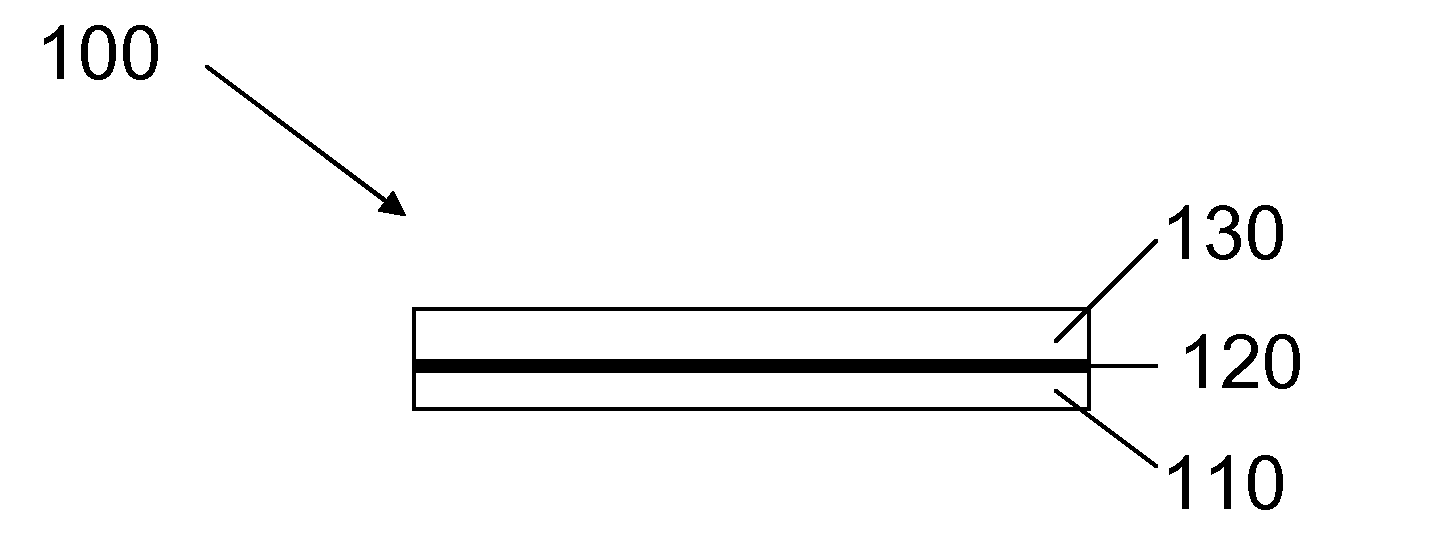
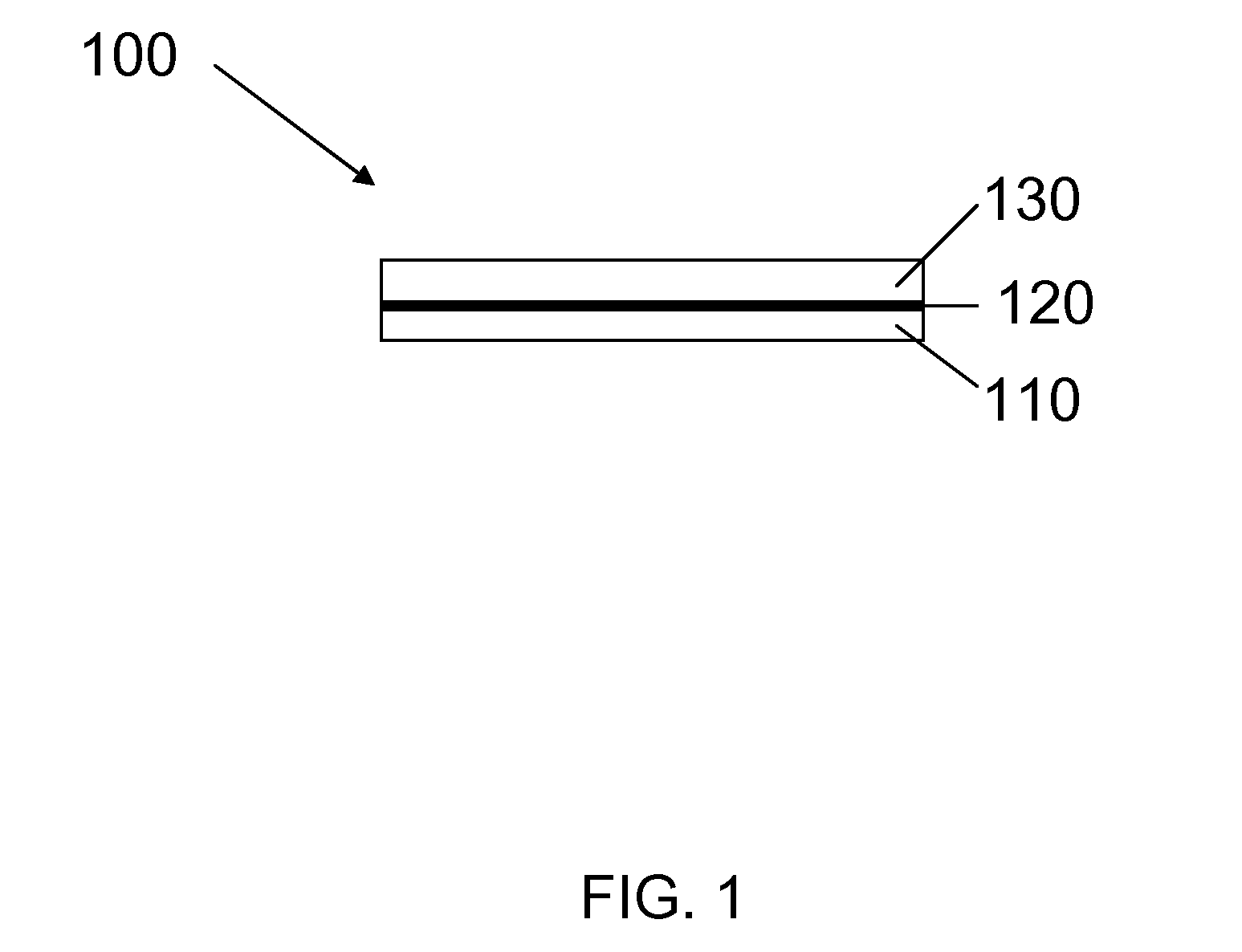
[0044]Two different multi-laminate hermetic sheets were prepared from about 125 micron thick polyethylene-naphthalate (PEN) plastic that was coated with about 2 microns of 870CHM material. Sample 1 comprised as-deposited CHM-coated PEN plastic, while Sample 2 comprised CHM-coated PEN plastic that was sintered at 140° C. for 2 hr. A comparative Sample 3 comprised un-coated PEN plastic.

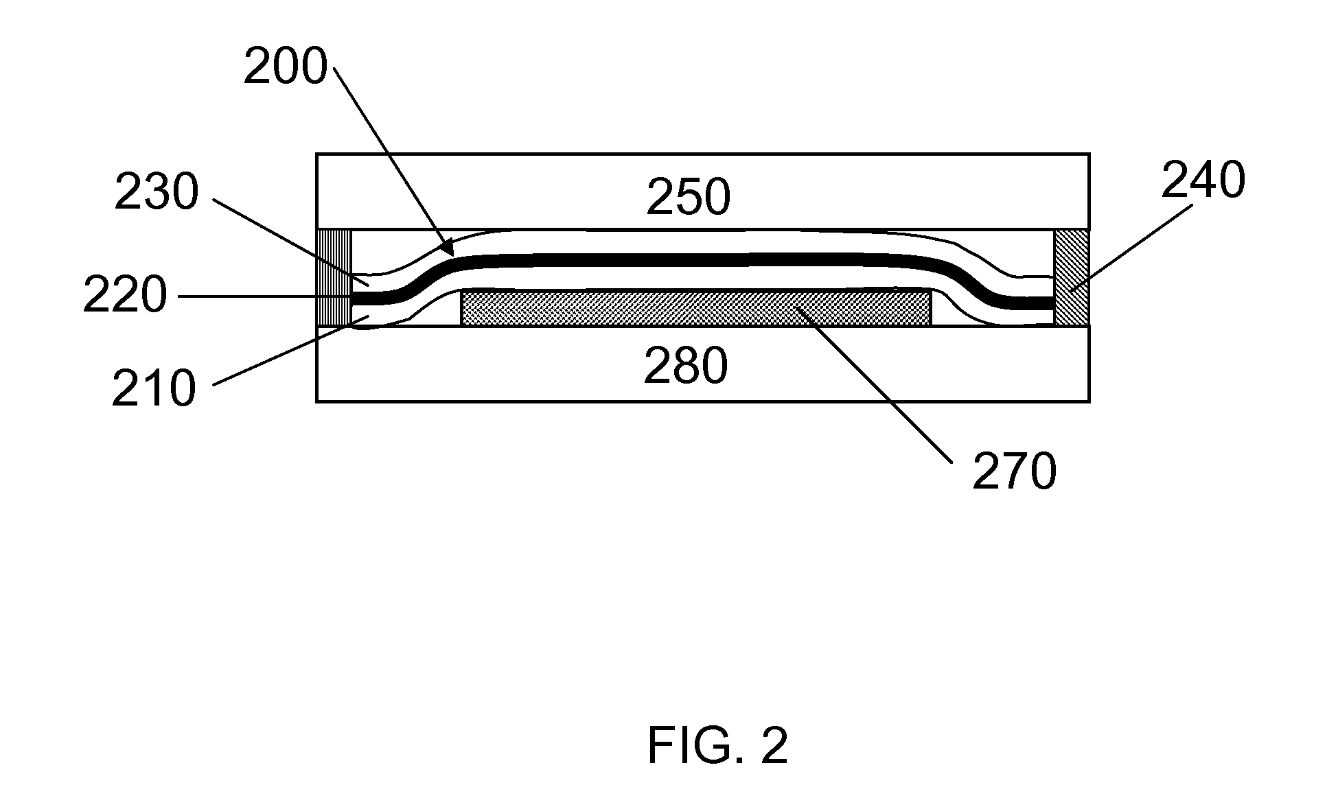
[0045]Test packets were formed by stacking two such sheets together and sealing around the periphery using an impulse sealer set to a temperature effective to form a seal. Prior to completely sealing the sheets together, Drierite™ material (calcium sulfate) was inserted into each packet as an indicator for when sufficient moisture had diffused into the packet to induce a color change in the Drierite™ from blue to pink. After 90 hrs in ambient humidity, the Drierite™ in comparative Sample 3 was pink, indicating that moisture had penetrated the packet. On the other hand, the content of both Sample 1 and S...


PUM

PropertyMeasurementUnit
thicknessaaaaaaaaaa
total thicknessaaaaaaaaaa
areaaaaaaaaaaa

Abstract

A free-standing multi-laminate hermetic sheet includes a first carrier film, a hermetic inorganic thin film formed over the first carrier film, and a second carrier film formed over the hermetic inorganic thin film. A workpiece can be hermetically sealed using the multi-laminate sheet, which can be applied to the workpiece in a step separate from a formation step of either the multi-laminate sheet or the workpiece.

Description

BACKGROUND AND SUMMARY[0001]The present disclosure relates generally to hermetic barrier layers, and more specifically to free-standing multi-laminate hermetic sheets, related structures, and methods of forming hermetic seals.[0002]Hermetic barrier layers can be used to protect sensitive materials from deleterious exposure to a wide variety of liquids and gases. As used herein, “hermetic” refers to a state of being completely or substantially sealed, especially against the escape or entry of water or air, though protection from exposure to other liquids and gases is contemplated.[0003]Approaches to creating hermetic barrier layers include physical vapor deposition (PVD) methods such as sputtering or evaporation, or chemical vapor deposition (CVD) methods such as plasma-enhanced CVD (PECVD) where a hermetic barrier layer can be formed directly on the device or material to be protected. By way of example, both reactive and non-reactive sputtering can be used to form a hermetic barrier...

Claims


Application Information

Patent Timeline
Patent Type & Authority Applications(United States)
IPC IPC(8): B32B27/00B32B1/04B32B7/00B32B37/00B32B27/36
CPCB32B27/36B32B27/32B32B3/04B32B2255/20Y10T428/231H01L51/5237Y10T428/24H01L51/5256Y10T428/239B32B2367/00Y10T428/263Y10T156/10B32B9/045B32B27/283B32B2307/412B32B2307/546B32B2307/554B32B2307/5825B32B2307/732B32B2439/70B32B2439/80B32B2457/12B32B2457/206Y10T428/31786Y10T428/31663Y10T428/249921H10K50/8445H10K50/841H10K50/8426H10K50/84
Inventor EDWARDS, VICTORIA ANNGIROUX, CYNTHIA BAKERKOVAL, SHARI ELIZABETHQUESADA, MARK ALEJANDROWALCZAK, WANDA JANINA
Owner CORNING INC
Why Eureka
Try Eureka