
High-power collimating lens assemblies, and methods of reducing the optical power density in collimating lens assemblies

a technology of collimating lens and high-power collimating, which is applied in the direction of optics, optical elements, instruments, etc., can solve the problems of adversely affecting the performance of collimators, high optical power densities, and irreversible darkening of epoxy and/or index-matching materials, etc., and achieve the effect of reducing optical power densities

Active Publication Date: 2011-10-27
MOOG INC
View PDF3 Cites 7 Cited by
  • Summary
  • Abstract
  • Description
  • Claims
  • Application Information

AI Technical Summary

Benefits of technology

[0017]In the improved collimating lens assembly, the step-index multimode fiber reduces the optical energy at the step-index multimode fiber distal end from that at the step-index multimode fiber proximal end, and the graded-index multimode fiber reduces the optical energy at the graded-index distal end from that at the graded-index multimode fiber proximal end.
[0019]In another aspect, the invention provides an improved method of reducing the optical power density in a collimating lens assembly (32) having a longitudinal axis (x-x). This method broadly includes the steps of: providing a singlemode fiber (38) terminating in a distal end; providing a step-index multimode fiber (44) having a proximal end and having a distal end; and positioning the singlemode fiber distal end to abut the step-index multimode fiber proximal end; providing a graded-index multimode fiber (45) having a proximal end and having a distal end; positioning the graded-index multimode fiber proximal end to abut the step-index multimode fiber distal end; providing a collimating lens (34); positioning the collimating lens in axially-spaced relation to the graded-index multimode fiber distal end; supplying optical power to the singlemode fiber at a density on the order of magnitude of that needed for one of wavelength division multiplexing and dense wavelength division multiplexing; reducing the optical power density at the graded-index multimode fiber distal end from that at the graded-index multimode fiber proximal end; and further reducing the optical power density at the step-index multimode fiber distal end from that at the step-index multimode fiber proximal end; thereby to cause collimated light of reduced optical power density to exit from the collimating lens assembly.
[0026]Another object is to provide an improved method of reducing the optical power density in collimating lens assemblies.

Problems solved by technology

However, problems develop when high levels of optical power are transmitted through epoxy, silicone gel and / or index-matching media.
For example, such epoxy and / or media will have a variable coefficient of thermal expansion, or a temperature-dependent refractive index that may adversely affect collimator performance.
Moreover, exposure to high optical power densities can irreversibly darken the epoxy and / or the index-matching material.
In addition to volume effects (i.e., changes occurring within the optical path of the collimator), detrimental effects may occur on the surface of the singlemode fiber.
This is particularly the case because the index-matching materials that would normally be in the interface between the singlemode fiber and the collimating ball lens, cannot be used.
Because of the high energy density that exists on the surface of a singlemode fiber when a high power level is transmitted, contaminants (e.g., ceramic particles from ferrules and alignment sleeves, dust, and other contaminants) can be heated to temperatures higher than the melting point of silica, which may result in cracking and pitting of the fiber surface.
However, there are inherent pointing accuracy issues with this type of design that precludes their use in a FORJ, where pointing accuracy is important.

Method used


Image

  • High-power collimating lens assemblies, and methods of reducing the optical power density in collimating lens assemblies
  • High-power collimating lens assemblies, and methods of reducing the optical power density in collimating lens assemblies
  • High-power collimating lens assemblies, and methods of reducing the optical power density in collimating lens assemblies

Examples


Embodiment Construction

[0035]At the outset, it should be clearly understood that like reference numerals are intended to identify the same structural elements, portions or surfaces consistently throughout the several drawing figures, as such elements, portions or surfaces may be further described or explained by the entire written specification, of which this detailed description is an integral part. Unless otherwise indicated, the drawings are intended to be read (e.g., cross-hatching, arrangement of parts, proportion, degree, etc.) together with the specification, and are to be considered a portion of the entire written description of this invention. As used in the following description, the terms “horizontal”, “vertical”, “left”, “right”, “up” and “down”, as well as adjectival and adverbial derivatives thereof (e.g., “horizontally”, “rightwardly”, “upwardly”, etc.), simply refer to the orientation of the illustrated structure as the particular drawing figure faces the reader. Similarly, the terms “inwa...


PUM

PropertyMeasurementUnit
axial lengthaaaaaaaaaa
distanceaaaaaaaaaa
distanceaaaaaaaaaa

Abstract

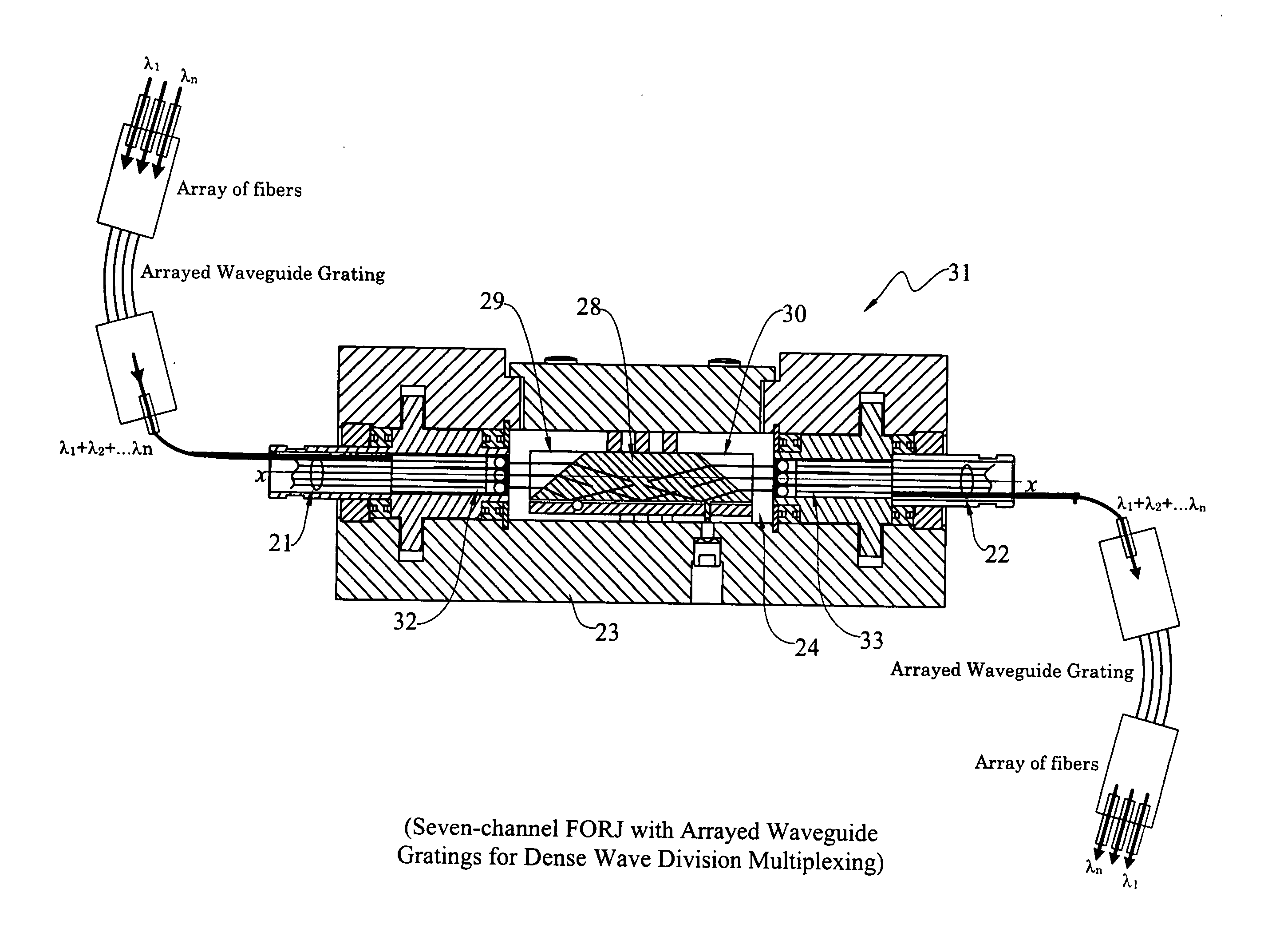
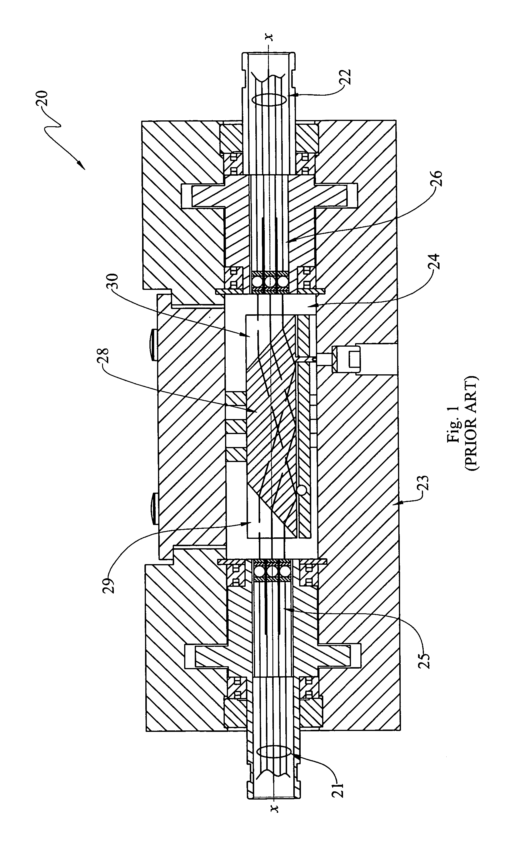
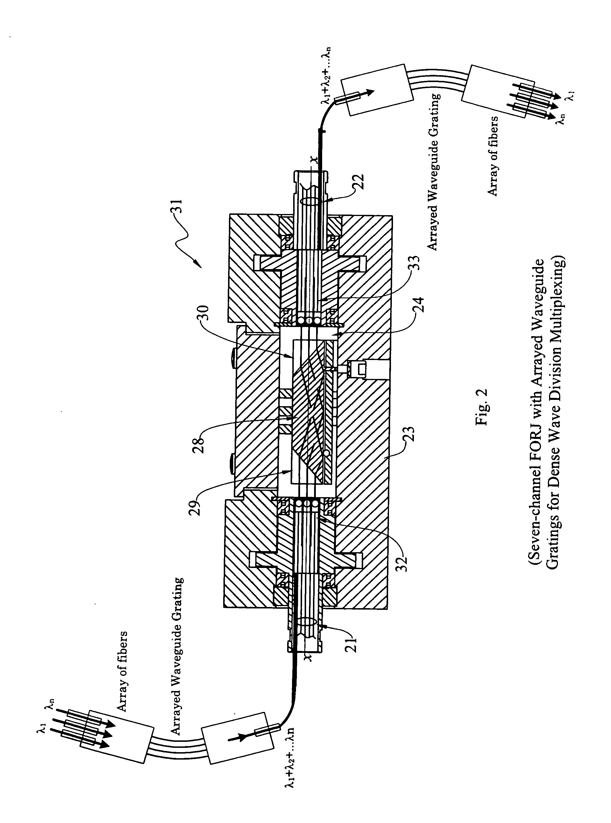
The present invention provides improved collimating lens assemblies (32), improved methods of reducing the optical power density in collimating lens assemblies, and to improved fiber optic rotary joints (31) incorporating such improved collimating lens assemblies. The improved collimating lens assembly broadly includes: a singlemode fiber (38) terminating in a distal end; a step-index multimode fiber (44) having a proximal end abutting to the singlemode fiber distal end, and having a distal end; a graded-index multimode fiber (45) having a proximal end abutting the step-index multimode fiber distal end, and having a distal end; and a collimating lens (34) longitudinally spaced from the graded-index multimode fiber distal end by an intermediate air gap (43), and operatively arranged to collimate light rays emanating from the graded-index multimode fiber distal end. The improved collimating lens assembly is characterized by the fact that there is no epoxy, silicone gel or index-matching material between the graded-index multimode fiber distal end and the collimating lens. Rather, these various elements are fusion-spliced together. The improved collimating lens assembly is capable of handling energy levels that are typically used in various wavelength division multiplexing techniques.

Description

TECHNICAL FIELD[0001]The present invention relates generally to fiber optic rotary joints and collimating lens assemblies, and, more particularly, to improved high-power collimating lens assemblies for use in such fiber optic rotary joints that may employ various wave division multiplexing techniques; to improved fiber optic rotary joints that incorporate such improved collimating lens assemblies; and to improved methods of reducing the optical power density in such collimating lens assemblies.BACKGROUND ART[0002]Fiber optic collimating and focusing assemblies, sometimes known as collimators, are used to launch a beam of light from one optical fiber into free space, and then to capture such light and redirect it into another fiber. Collimators (i.e., optical devices for emitting parallel rays of light) are usually necessary whenever the free space propagation exceeds several hundred microns (“μm”; 1 μm=0.001 mm). For this reason, collimators are commonly used in fiber optic rotary j...

Claims


Application Information

Patent Timeline
Patent Type & Authority Applications(United States)
IPC IPC(8): G02B6/32G02B6/255
CPCG02B6/3604G02B6/32Y10T29/49195G02B6/3813
Inventor LEWIS, NORRIS E.OOSTERHUIS, MARTIN J.LO, K. PETER
Owner MOOG INC
Learn More