
Welding Electrode With Contoured Face

a welding electrode and contoured face technology, applied in the direction of electrode maintenance, soldering apparatus, manufacturing tools, etc., can solve the problems of uneven thickness of the electrode, and inability to spot weld one of the materials, etc., to achieve the effect of reducing the thickness of the surface, reducing the effectiveness of the texture used, and reducing the strength of the electrod

Active Publication Date: 2011-11-03
GM GLOBAL TECH OPERATIONS LLC
View PDF0 Cites 22 Cited by
  • Summary
  • Abstract
  • Description
  • Claims
  • Application Information

AI Technical Summary

Benefits of technology

[0010]A method for welding a plurality of aluminum to aluminum welds and a plurality of steel to steel welds using the same welder includes providing a resistance spot welder with a pair of weld electrodes having an electrode face radius of curvature in the range between 20 mm and 40 mm. The electrode material is selected with sufficient high temperature strength that the steel welding process does not excessively soften the electrode and harm the effectiveness of the texture used for ...

Problems solved by technology

With regard to the use of a copper electrode to weld aluminum panels, it is known that a buildup of aluminum from the aluminum sheet onto the electrode face can result in the formation of a low-melting-point Cu—Al eutectic that eventually produces pits in the electrode's surface.
Thus, although the prior art has developed techniques for welding steel to steel, and techniques for welding aluminum to aluminum, the welding of steel to steel and aluminum to aluminum using one welding gun has not been done for two primary reasons.
First, welding electrodes designed to spot weld one of the materials are typically not suitable for spot welding the other material.
For example, a ballnose electrode used to spot weld steel causes excessive sheet deformation and weld metal expulsion when used to spot weld aluminum.
Second, contamination of aluminum panels by iron-containing particles transferred by the welding electrode could cause galvanic corrosion and premature panel deterioration.

Method used


Image

  • Welding Electrode With Contoured Face
  • Welding Electrode With Contoured Face
  • Welding Electrode With Contoured Face

Examples


Embodiment Construction

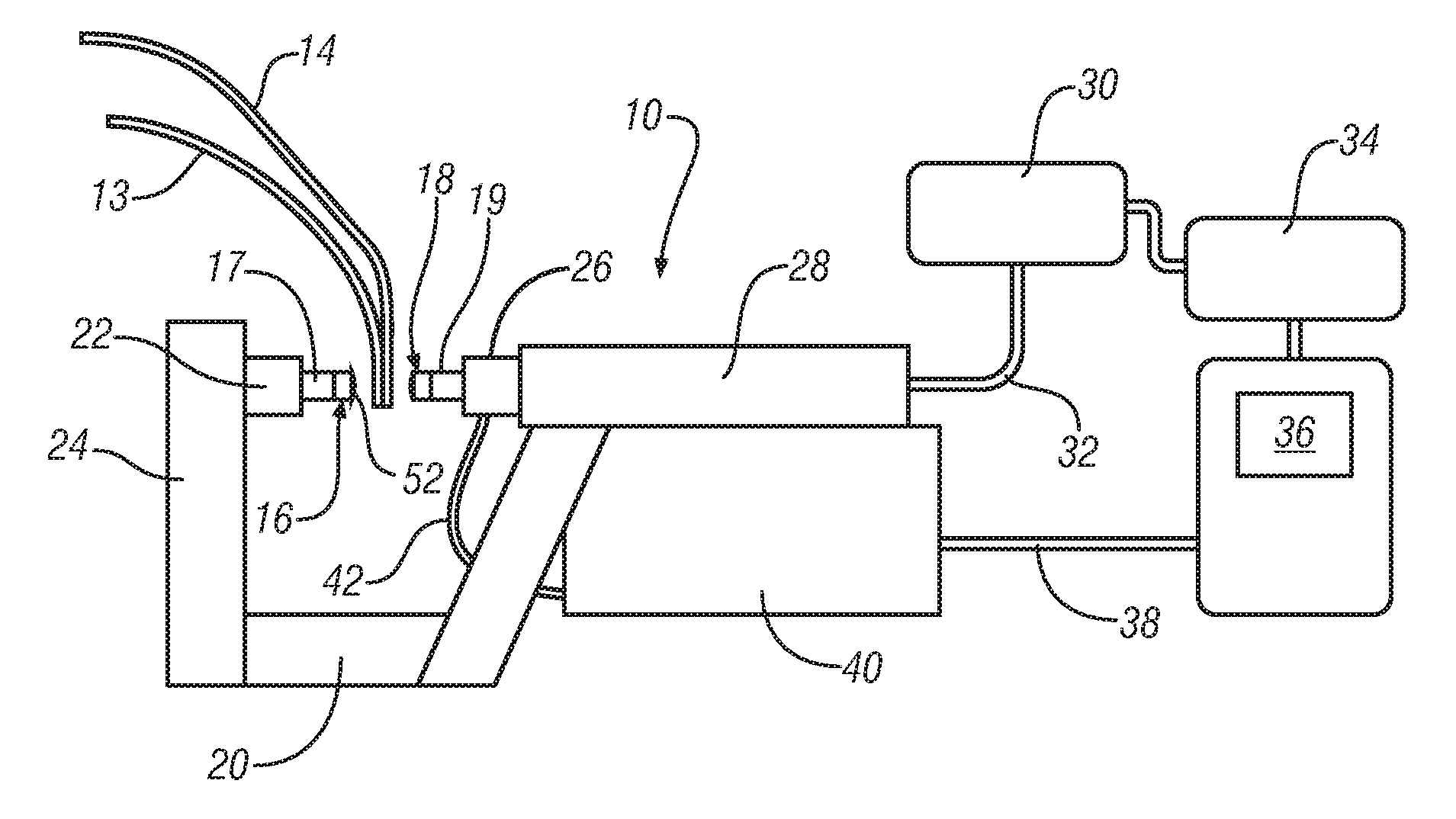
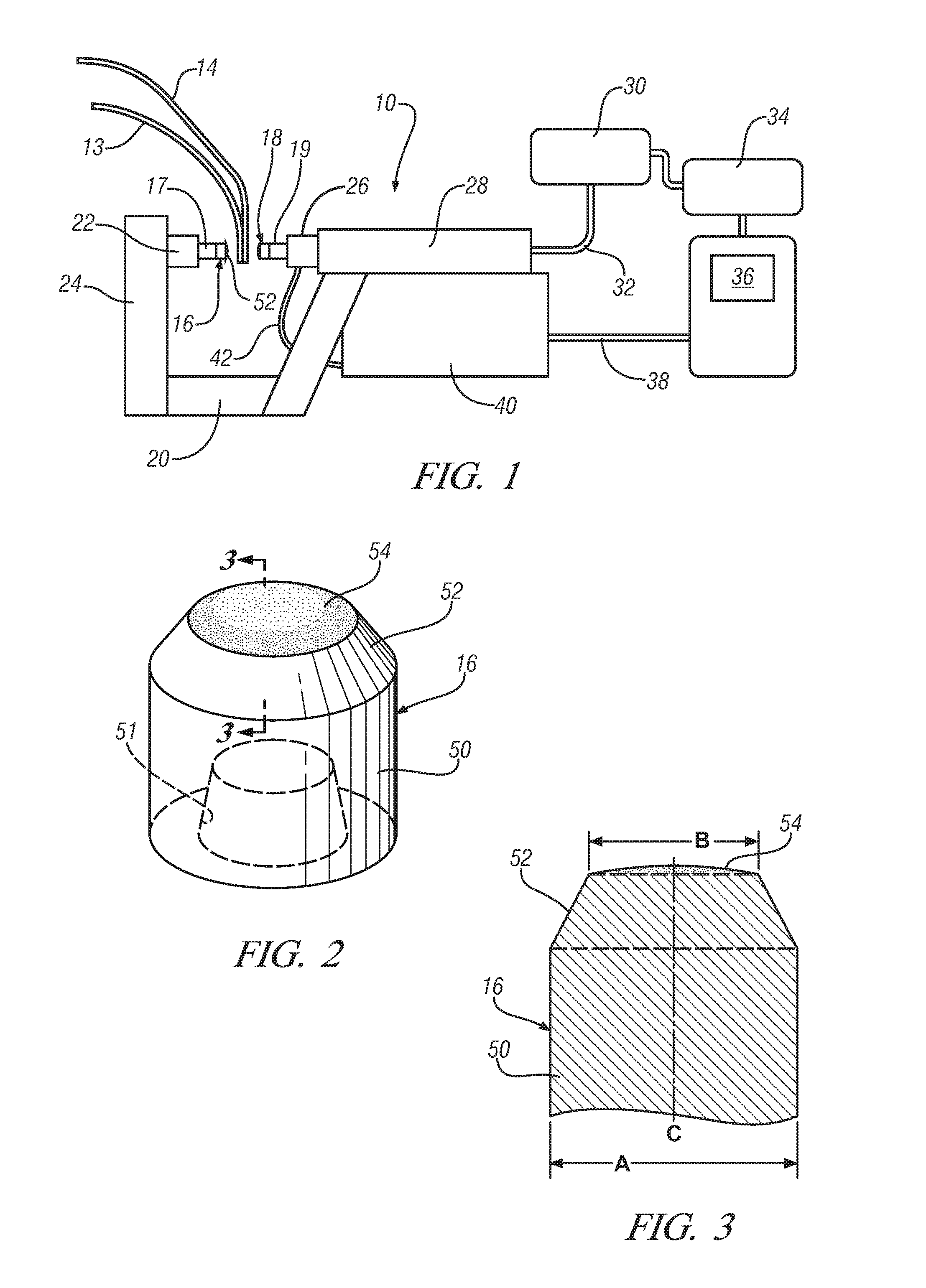
[0019]FIG. 1 is a schematic illustration of a side view of a representative spot welding gun apparatus 10 with the associated equipment utilized in spot welding operations. In such an operation, an assembly of two or more sheet metal panels 13 and 14 to be welded is prepared and delivered by a conveyor or other device, to the welding gun apparatus 10. The welding gun apparatus 10 is typically mounted on a robot which moves the welding gun apparatus 10 along the sheet metal panels 13 and 14 to rapidly accomplish a succession of individual electric resistance spot welds. The metal panels 13 and 14 can both be of aluminum, or can both be steel.

[0020]In FIG. 1, the metal panels 13 and 14 are shown poised between a pair of axially aligned and opposing electrodes 16 and 18 of a welding gun arm 20. The gun arm 20 is in the configuration of a C so that the opposing electrodes 16 and 18 can be brought to bear and press upon opposite sides of the metal panels 13 and 14. In the arrangement sho...


PUM

PropertyMeasurementUnit
Temperatureaaaaaaaaaa
Lengthaaaaaaaaaa
Lengthaaaaaaaaaa

Abstract

A method for welding a plurality of aluminum to aluminum welds and a plurality of steel to steel welds using the same welder includes providing a resistance spot welder with a pair of weld electrodes having an electrode face radius of curvature in the range between 20 mm and 40 mm. The series of aluminum to aluminum welds is first made, and then, after completing the aluminum to aluminum welds, the series of steel to steel welds are made. After completing the steel to steel welds the weld electrodes are cleaned by an abrasive to remove any buildup or contamination of aluminum on the electrodes. In the event the electrodes have mushroomed, then dressing of the electrodes is provided and then the abrasive cleaning is performed to restore the surface texture.

Description

FIELD OF THE INVENTION[0001]The present invention relates to welding together metal panels and more particularly provides a method for the resistance spot welding together of both aluminum to aluminum panels and steel to steel panels using a single weld gun.BACKGROUND OF THE INVENTION[0002]Automotive vehicle body manufacturing operations include the joining together of two sheet metal layers by resistance spot welding. The spot welding operation is typically accomplished by assembling the sheet metal panels in a suitable fixture or other clamping apparatus and then pressing welding electrodes against opposite sides of adjoining metal panels. The weld electrodes provide both clamping force and also communicate weld current to the point of contact with the metal panels.[0003]The weld gun is typically operated by a robot so that a succession of welds can be made in a particular manufacturing cell. Manufacturing efficiencies demand that the welds be made in very rapid succession as fast...

Claims


Application Information

Patent Timeline
IPC IPC(8): B23K11/11
CPCB23K11/115B23K11/3063B23K2203/10B23K35/302B23K2203/04B23K35/222B23K2103/04B23K2103/10B23K11/20B23K11/3009B23K35/0205
Inventor SIGLER, DAVID R.KARAGOULIS, MICHAEL J.
Owner GM GLOBAL TECH OPERATIONS LLC
Learn More