Manufacturing systems with reactor units

Inactive Publication Date: 2011-11-10
MEKTECH COMPOSITES
View PDF2 Cites 4 Cited by
  • Summary
  • Abstract
  • Description
  • Claims
  • Application Information

AI Technical Summary

Benefits of technology

[0010]In some embodiments, a manufacturing system includes a mold configured to form a molded article, a reactor unit, and an exhaust line. The reactor unit includes media made of a collector material and a reactive material. The collector material is selected from at least one of acti

Problems solved by technology

Manufacturing processes can generate byproducts that may pollute the atmosphere.
Such byproducts ma

Method used


Image

  • Manufacturing systems with reactor units
  • Manufacturing systems with reactor units
  • Manufacturing systems with reactor units

Examples


Embodiment Construction

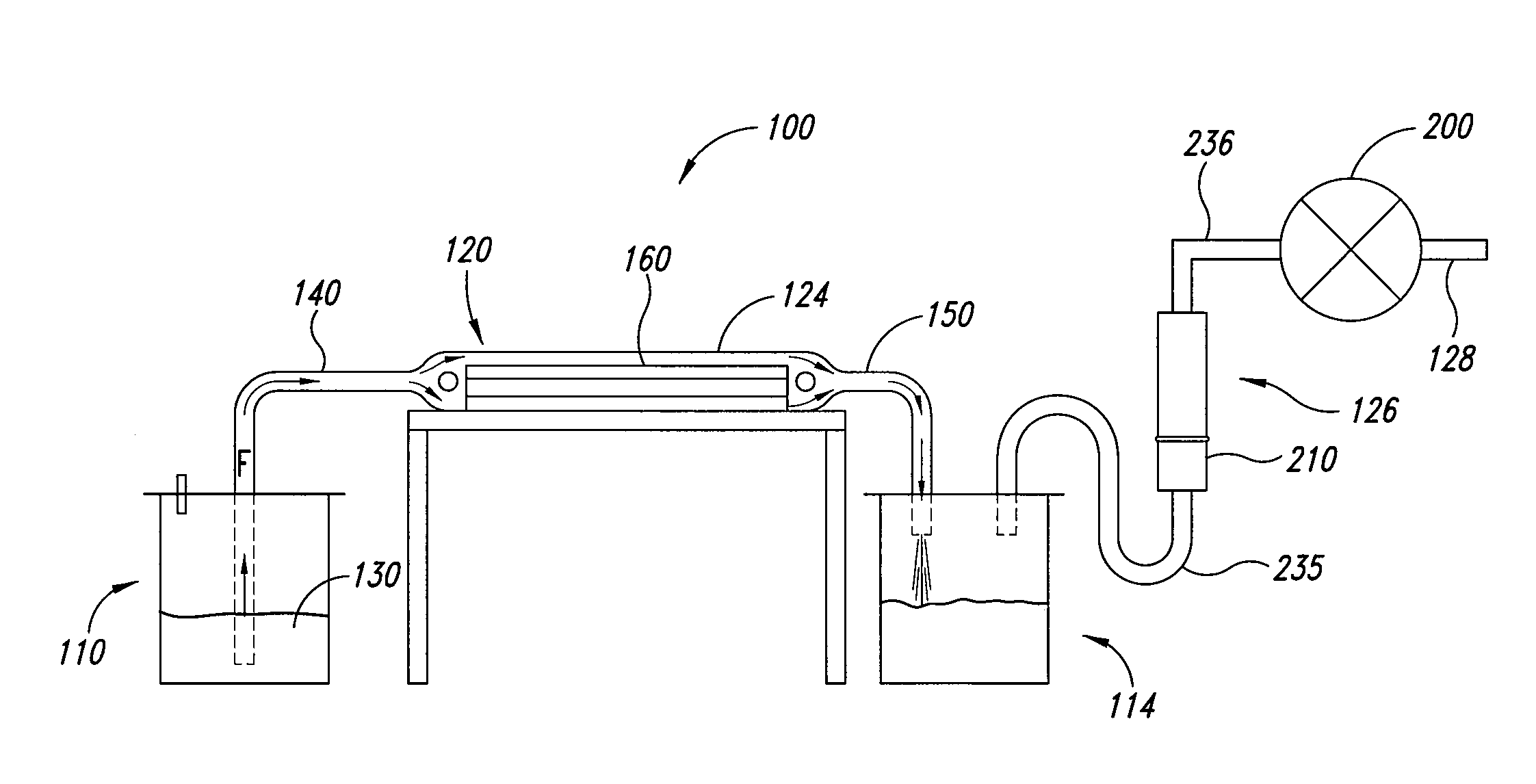
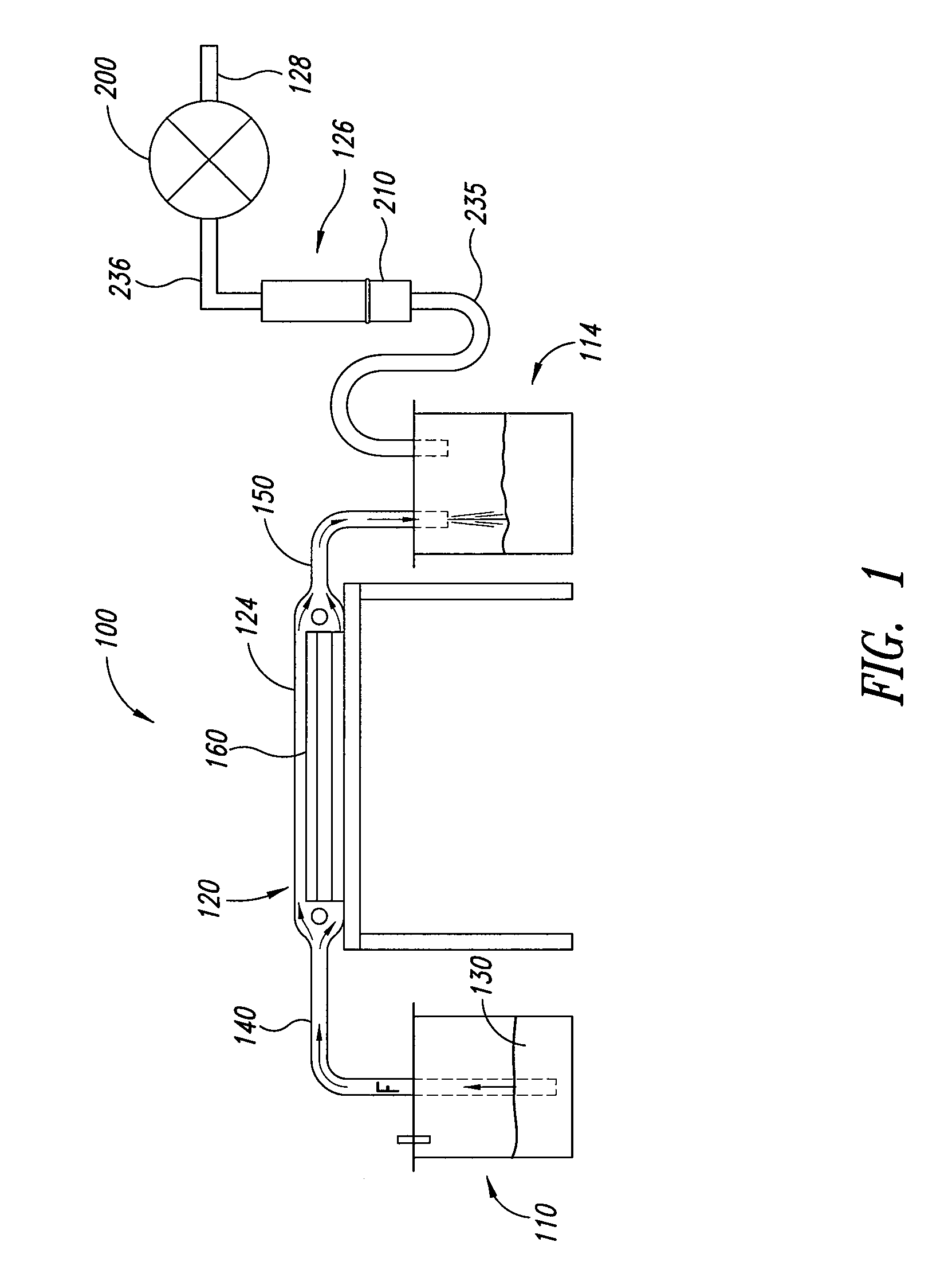
[0021]FIG. 1 shows a manufacturing system 100 that includes a feed tank 110, a collection tank 114, and a mold 120 for receiving moldable material 130 from the feed tank 110 and delivering the moldable material 130 to the collection tank 114. Pollutants in the tank 114 are drawn into a treatment system 126. A reactor unit 210 of the system 126 removes pollutants in an exhaust stream (e.g., a stream of fumes and air) before exhausting the stream to the atmosphere via a vent 128. The treatment system 126 can keep emissions of pollutants at or below a desired level.

[0022]The moldable material 130 can be a thermoset, thermoplastic, elastomer, rubber, or the like. Exemplary thermosets include, but are not limited to, epoxy, phenolic resins, melamine-formaldehyde, urea-formaldehyde, polyesters, vinyl toluene, and vinyl esters. These materials can emit byproducts during processing (e.g., curing). The moldable material 130 in the tank 110 can flow through a feed line 140 into the mold 120. ...


PUM

PropertyMeasurementUnit
Fractionaaaaaaaaaa
Fractionaaaaaaaaaa
Timeaaaaaaaaaa

Abstract

A reactor unit includes a bed of desiccant and a bed of media for treating pollutants. The media includes an adsorptive material and a reactive material. The adsorptive material is selected from at least one of activated carbon and zeolite. The reactive material is selected from at least one of potassium permanganate and sodium hydroxide. The adsorptive material is impregnated with reactive materials to enhance performance. A method of using the reactor unit includes delivering a moldable material into a mold. An effluent stream carrying pollutants produced by the moldable material flows through the reactor unit.

Description

CROSS-REFERENCE TO RELATED APPLICATION[0001]This application claims the benefit under 35 U.S.C. §119(e) of U.S. Provisional Patent Application No. 61 / 144,681 filed Jan. 14, 2009. This provisional application is incorporated herein by reference in its entirety.BACKGROUND[0002]1. Technical Field[0003]The present disclosure generally relates to manufacturing systems, and more specifically, to manufacturing systems with reactor units.[0004]2. Description of the Related Art[0005]Conventional manufacturing processes often generate byproducts that pollute the surrounding atmosphere and often present health risks. Phenolic resins, styrenated resins, and styrene derivative resins are commonly used manufacturing materials that produce such unwanted byproducts. Workers often wear respirators for protection from such pollutants. Unfortunately, respirators may malfunction, may not adequately remove pollutants, and may be relatively expensive. Additionally, it may be difficult to dispose of the p...

Claims


Application Information

Patent Timeline
IPC IPC(8): B01D15/00B30B15/00B01J8/00
CPCB01D53/04B01J2220/46B01D53/82B01D2251/304B01D2251/306B01D2253/102B01D2253/108B01D2257/704B01D2257/80B01D2259/4146B01J20/02B01J20/18B01J20/20B01J20/28052B01J20/3204B01J20/3236B01D53/72
Inventor LEWARK, SR., BLAISE A.
Owner MEKTECH COMPOSITES
Why Eureka
Try Eureka