Ophthalmic apparatus, adaptive optical system, and image generating apparatus

a technology of optical system and image generating apparatus, applied in the field of optical system and adaptive optical system, can solve the problems of large optical system size, and high-order aberration of transmitted light wavefront, and achieve the effect of compact siz

Active Publication Date: 2011-11-17
CANON KK
View PDF2 Cites 19 Cited by
  • Summary
  • Abstract
  • Description
  • Claims
  • Application Information

AI Technical Summary

Benefits of technology

[0017]The present invention provides an ad

Problems solved by technology

Such imperfection causes high-order aberration on the wavefront of transmitted light.
Even if, therefore, a thick beam is made to strike the eye, a spot on the retina cannot be condensed to a desired diameter but rather spreads.
The first problem in the adaptive optical system is that the size of the optical system is large.
In addition, the correction strokes of such devices are short.
This, however, decreases the number of segments (pixels) effective at the time of correction, resulting in a deterioration in correction performance especially for high-order aberration.
Howev

Method used


Image

  • Ophthalmic apparatus, adaptive optical system, and image generating apparatus
  • Ophthalmic apparatus, adaptive optical system, and image generating apparatus
  • Ophthalmic apparatus, adaptive optical system, and image generating apparatus

Examples


first embodiment

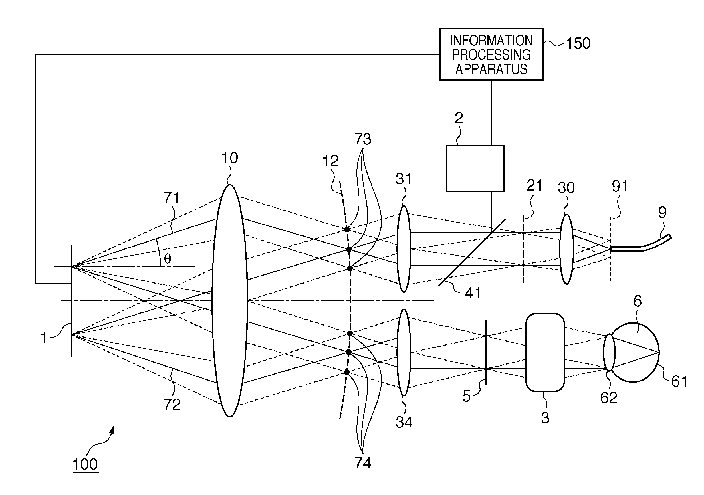
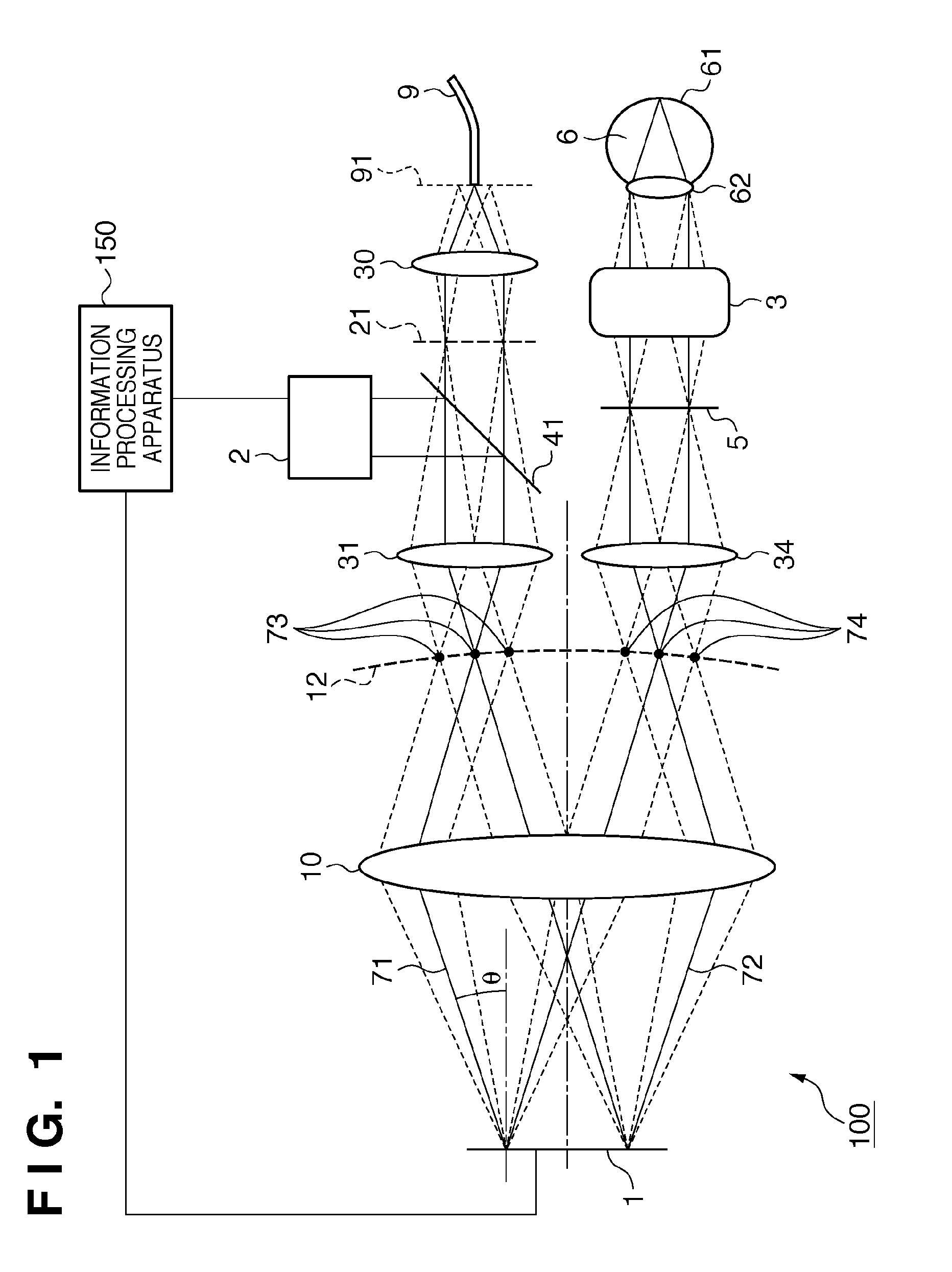
[0031]An adaptive optical system according to an embodiment of the present invention will be described with reference to FIG. 1. Referring to FIG. 1, the solid lines indicate light beams showing the image formation relationship between laser beams irradiated from an optical fiber 9, and the broken lines indicate light beams indicating the image formation relationship between the pupils of the optical systems. An adaptive optical system 100 is a confocal optical system constituted by an adaptive optical system and an ocular optical system, with a plane including an end portion (fiber end) of the optical fiber 9, which irradiates laser beams, being an object plane 91, and a retina 61 of an eyeball 6 being an image plane.

[0032]Light from a light source (not shown) which propagates through the optical fiber 9 is irradiated as divergent light from a fiber end and collimated by a collimator lens 30. The collimated light beam is then transmitted through a beam branching member 41 and conde...

second embodiment

[0048]The arrangement of an adaptive optical system 102 according to the second embodiment will be described with reference to FIG. 6. The adaptive optical system of this embodiment corrects wavefront aberration by using two deformable mirrors 1a and 1b as two wavefront correction devices. The displacement amount of a deformable mirror of a type having many displacement segments for changing the shape is limited to about several μm in most cases. In contrast, a deformable mirror of a type having a large displacement amount of several tens μm has few segments, and hence cannot reproduce a shape represented by a high-order function. For this reason, it is impossible to correct high-order aberration by using only a deformable mirror of a type having a large displacement amount. The adaptive optical system 102 of this embodiment includes both the different types of deformable mirrors 1a and 1b to correct high-order wavefront aberration by using the former type and correct low-order wave...

third embodiment

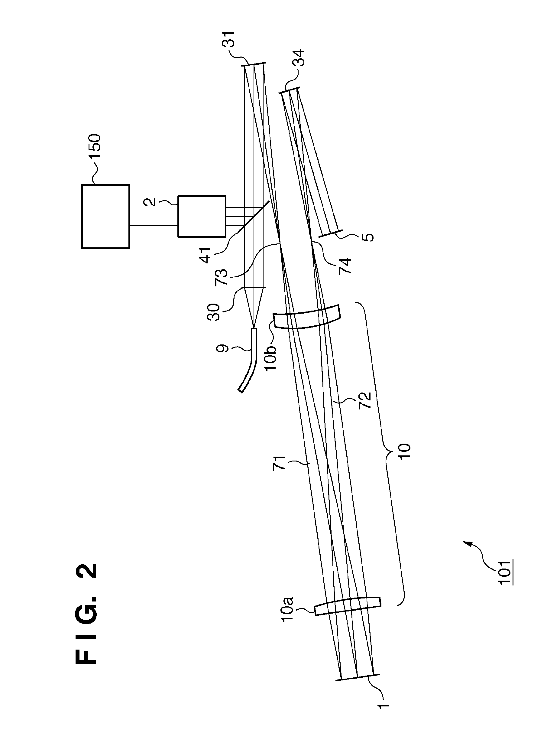
[0053]The arrangement of an adaptive optical system 103 according to the third embodiment will be described with reference to FIG. 7. This embodiment will exemplify an arrangement using a concave mirror 10c as a common optical system. The same reference numerals as in FIGS. 1 and 2 denote the same parts in FIG. 7, and a description of them will be omitted.

[0054]An optical element 31 (lens) forms the beam emitted from a light source (not shown) and collimated by a collimator lens through an optical fiber into a first intermediate image 73. The beam is then collimated by the concave mirror 10c and strikes a wavefront correction device 1. The beam reflected by the wavefront correction device 1 strikes the concave mirror 10c again. The beam reflected by the concave mirror 10c then forms a second intermediate image 74. The beam is collimated by an optical element 34 (lens) and guided to a deflection element 5 (scanner). At this time, a position corresponding to a wavefront sensor 2, the ...


PUM


Abstract

An ophthalmic apparatus includes an aberration correction unit which corrects aberration occurring in light irradiating an eye to be examined; and a common optical system which is commonly provided for an optical path of irradiated light on the aberration correction unit and an optical path of reflected light from the aberration correction unit. The common optical system includes at least one optical element, and areas through which the irradiated light and the reflected light respectively pass overlap each other on the optical element.

Description

BACKGROUND OF THE INVENTION[0001]1. Field of the Invention[0002]The present invention relates to an ophthalmic apparatus, an adaptive optical system, and an image generating apparatus using the adaptive optical system and, more particularly, to an adaptive optical system which corrects wavefront aberration occurring at an object to be detected and an image generating apparatus including the adaptive optical system.[0003]2. Description of the Related Art[0004]Recently, a technique of adaptive optics (adaptive optical technique) which corrects low- to high-order wavefront aberrations by an adaptive optical system using an optical element capable of actively correcting optical characteristics has been put into practice and applied to various fields. This technique corrects high-order wavefront aberration by a wavefront aberration correction device such as a deformable mirror or a spatial optical modulator by sequentially measuring the wavefront aberration of probe light or signal light...

Claims


Application Information

Patent Timeline
IPC IPC(8): A61B3/10G01J1/20
CPCA61B3/1015G02B26/06A61B3/1225A61B3/1025A61B3/14
Inventor SAITO, KENICHI
Owner CANON KK
Why Eureka
Try Eureka