If the
pulse energy is too low, then the link may be incompletely removed.
In cases where the energy per pulse exceeds the allowable energy
process window, excess pulse energy may be coupled into adjacent or underlying link structures, or the substrate itself, thereby causing highly undesirable damage to the device.
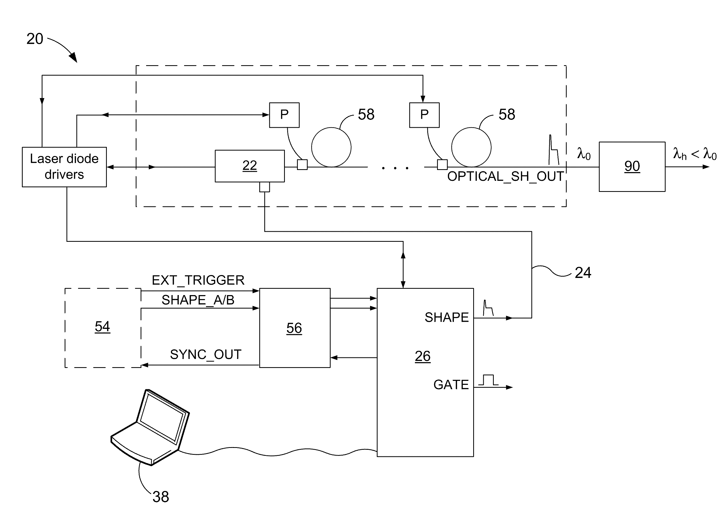
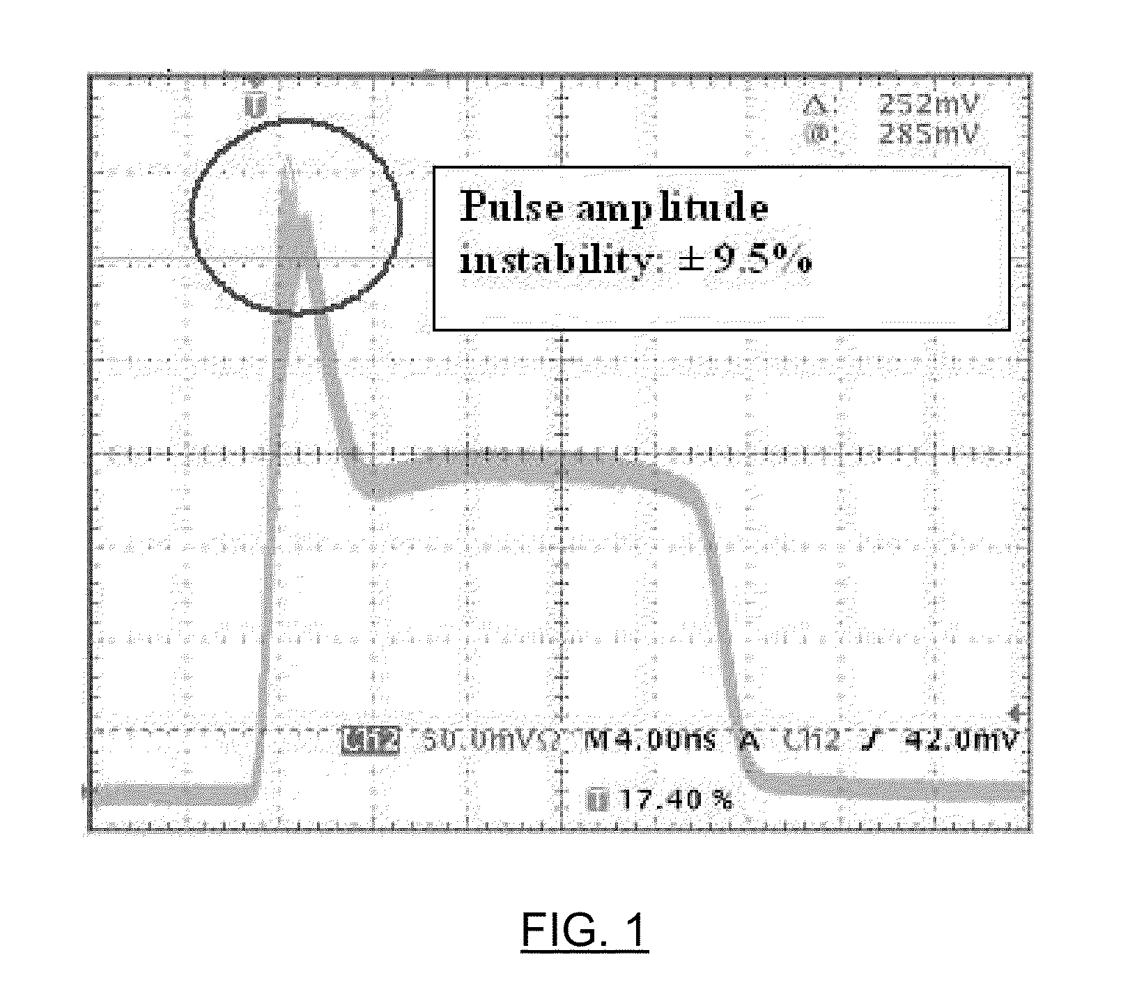
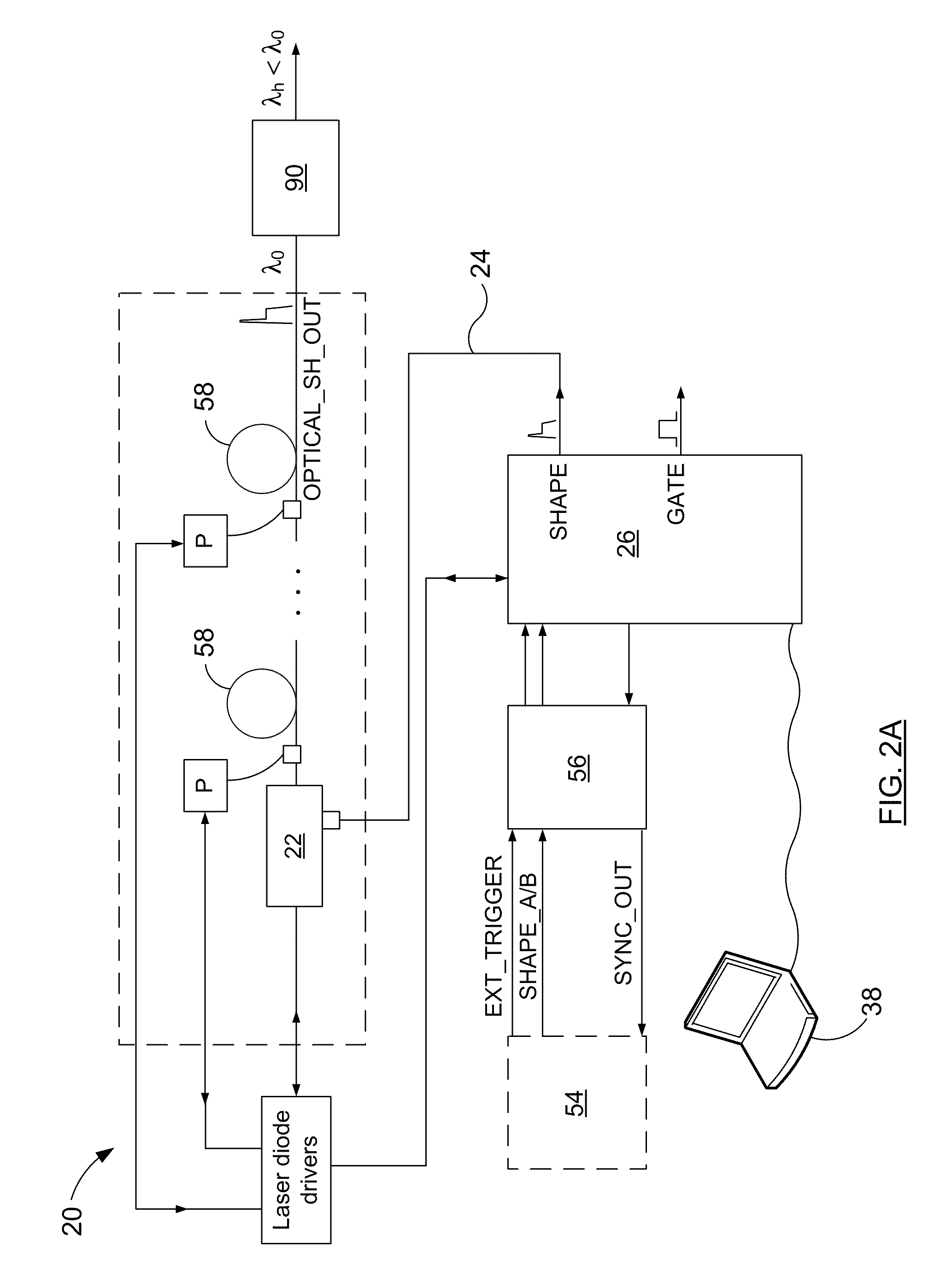
For
pulsed laser systems employing a directly modulated seed
laser diode, a commonly encountered difficulty is obtaining a satisfactory optical pulse amplitude stability on the
leading edge of the pulse, as switching transients often take place in the diode during the transitory regime corresponding to the
leading edge of the
current pulse.
In general, the spike amplitude varies from pulse to pulse, leading to poor peak power stability at the pulse
leading edge.
Parasitic capacitances and inductances associated with the details of the
laser diode physical characteristics and packaging can also contribute to create
noise at the current transitions.
As those skilled in the art will recognize, this effect is often worsened when the pulsed oscillator output is amplified and frequency converted to one or more
harmonic wavelengths using the process of nonlinear
harmonic conversion, as is well known in the art.
Other issues can arise from the presence of peak power instabilities.
For example, when
fiber amplifiers are used to amplify the pulsed seed signal, excessive peak power induced by the transient behavior can trigger the onset of Stimulated
Brillouin Scattering (SBS) or other nonlinear processes in the fibers, which can degrade the performances of the laser and in some cases even cause damage to it.
However this method is not very attractive for pulsed lasers having a MOPA architecture and relying on a directly modulated
semiconductor laser, because the pedestal (d.c.) current would generate a
continuous wave emission background between the pulses, which in turn would deplete the
population inversion in the subsequent
amplifier stage by
stimulated emission.
Another drawback associated with the continuous background is that the
optical power emitted between the triggered optical pulses can cause damage to the work piece between the different targets.
Even in its field of use, the method of CLAVERIE suffers from the drawback of shortening the lifetime of the
semiconductor laser, as mentioned by DUFOUR in U.S. Pat. No. 4,817,097, entitled “Method of and device for pulse-mode driving a semi-conductor laser”.
Although this method would certainly work better than the method of CLAVERIE in the context of pulsed laser oscillators having MOPA architectures (as the inter-pulse background would not be present), it imposes a more complex
laser diode driving circuit, which represents an additional cost.
Furthermore, as those skilled in the art will recognize, an increased component count in the vicinity of the laser diode
package usually represents additional difficulties for reaching fast rise times and fall times, because the complex impedance usually increases along with the circuit
footprint.

