Nerve-penetrating apparatus and method for optical and/or electrical nerve stimulation of peripheral nerves

a peripheral nerve and nerve penetrating technology, which is applied in the field of laser stimulation of animal tissues, can solve the problems of limiting the possibility of sub-fascicular selectivity when using electrical stimulation, affecting function, and affecting pressure and joint sensation, so as to achieve more reliable generation of nerve-action potential signals, more efficacy, and higher precision

Active Publication Date: 2011-12-01
NUROTONE MEDICAL LTD
View PDF9 Cites 46 Cited by
  • Summary
  • Abstract
  • Description
  • Claims
  • Application Information

AI Technical Summary

Benefits of technology

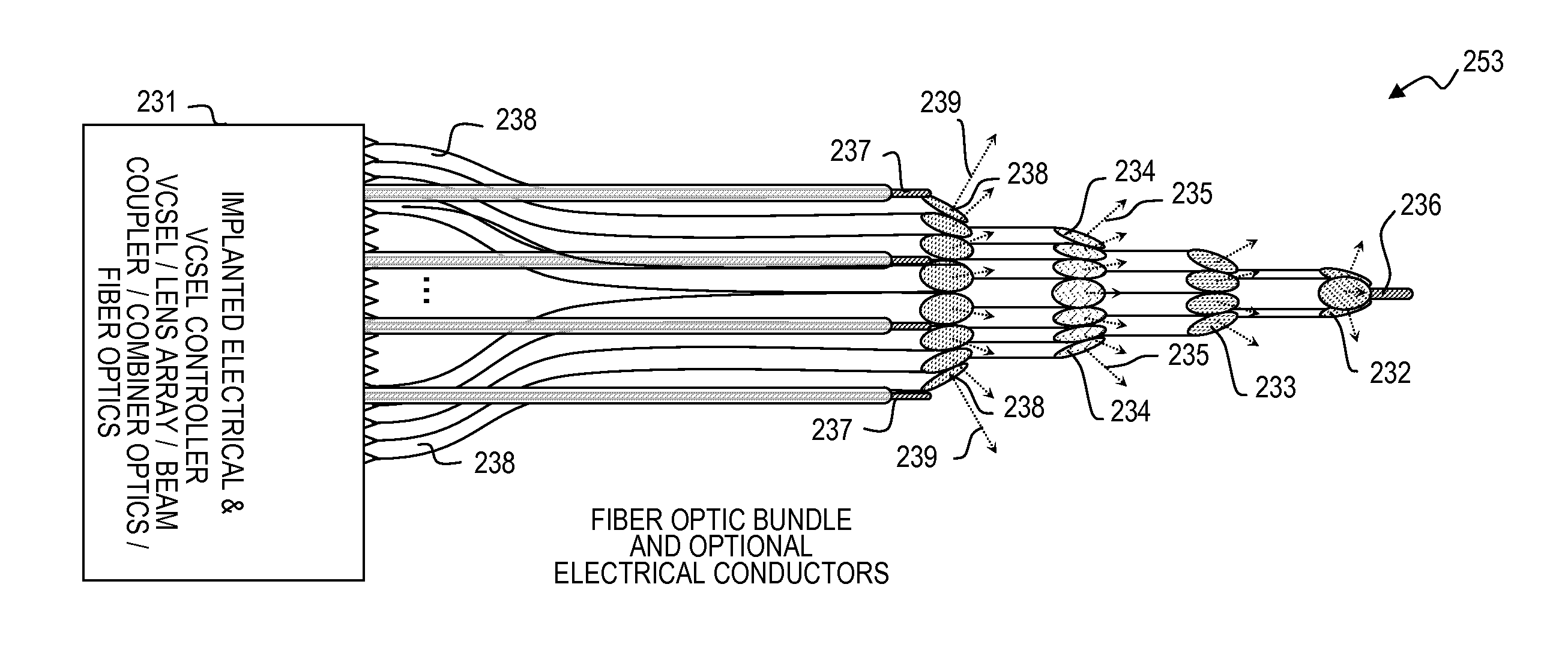
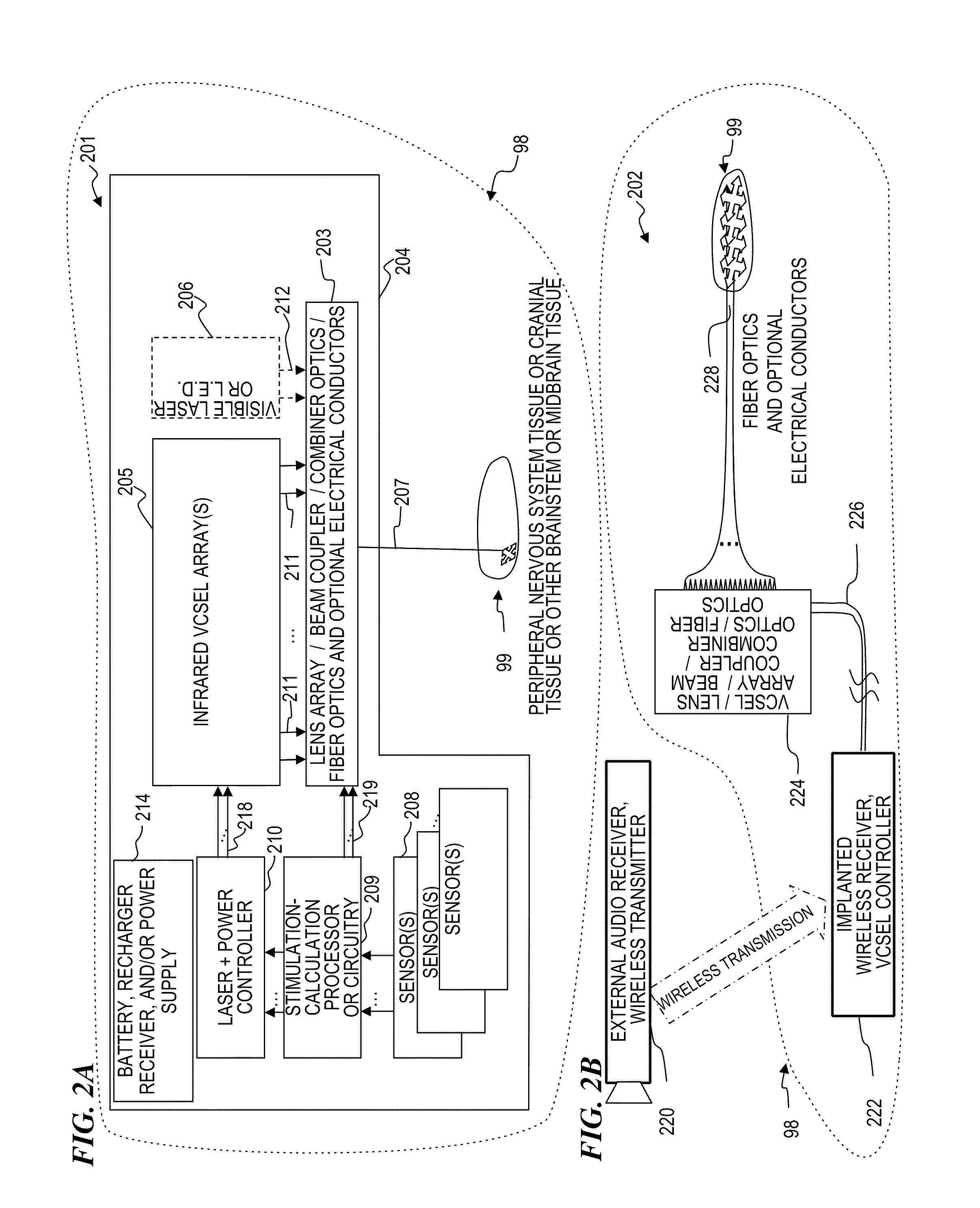
The present invention provides an apparatus and a method for optically, or optically and electrically, stimulating neurons (e.g., sensory and/or motor neurons) in the peripheral nervous system (PNS), and or the central nervous system (CNS) (including the spinal cord and/or brainstem and/or midbrain and/or brain tissue of a living animal) to obtain a physiological response in the animal (e.g., a sense of touch, taste, smell, sight or sound). In some embodiments, the simultaneous application of both an optical stimulation signal and an electrical stimulation signal provides more efficacious generation o

Problems solved by technology

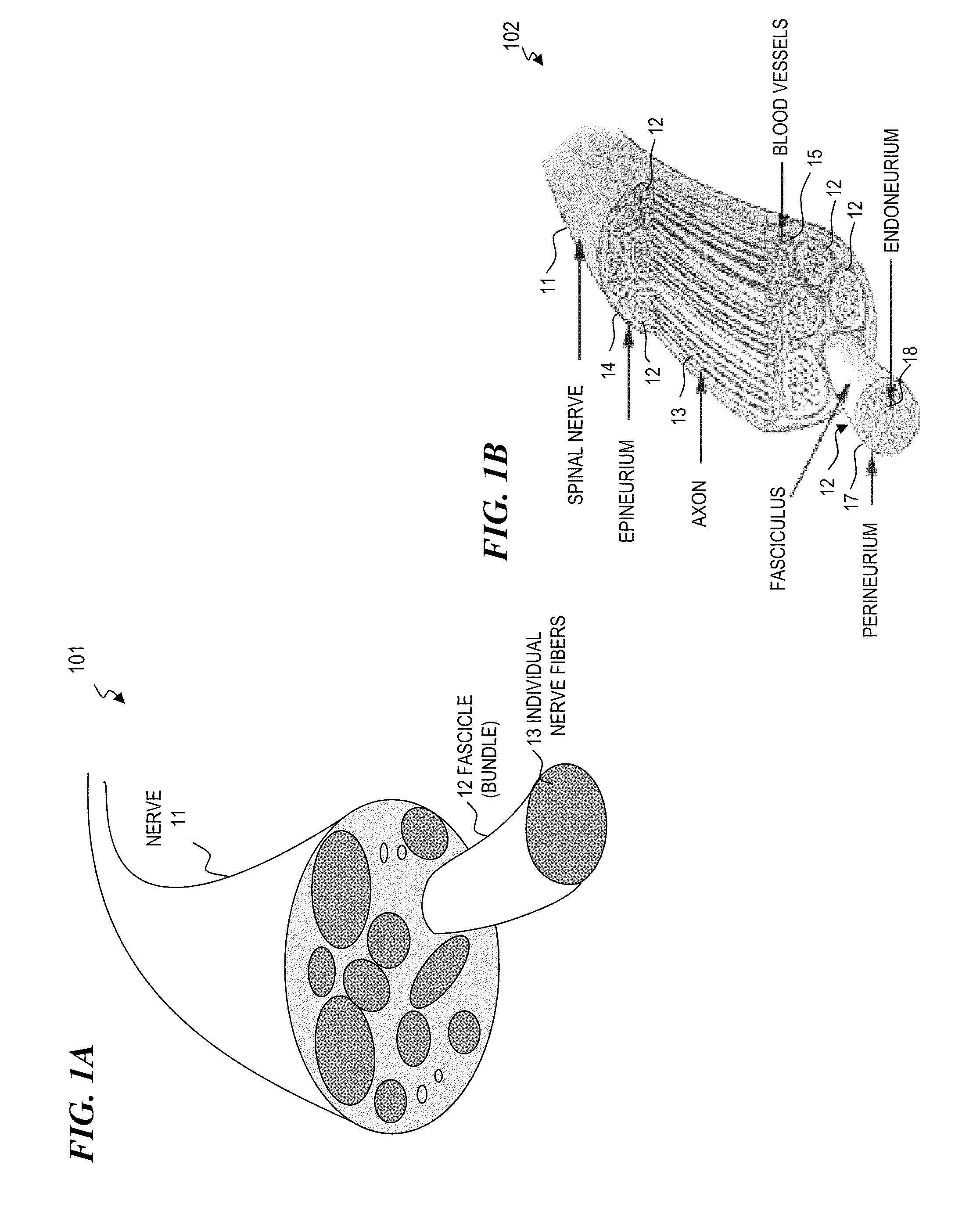
One disadvantage of using electrical stimulation is that the electrical signal applied to stimulate one nerve fiber will generally stimulate a plurality of surrounding nerve fibers (even nerve fibers in other fascicles than the fascicle containing the nerve of interest) to also trigger NAP signals in those other nerve fibers: Present conventional neuromodulation technology is based on the generation of electric fields around the neuron.
This causes the voltage distribution to be fairly uniform within at least a portion of a fascicle (while also being electrically isolated from neighboring fascicles), hence limiting the possibility of sub-fascicular selectivity when using elec

Method used


Image

  • Nerve-penetrating apparatus and method for optical and/or electrical nerve stimulation of peripheral nerves
  • Nerve-penetrating apparatus and method for optical and/or electrical nerve stimulation of peripheral nerves
  • Nerve-penetrating apparatus and method for optical and/or electrical nerve stimulation of peripheral nerves

Examples


Embodiment Construction

Although the following detailed description contains many specifics for the purpose of illustration, a person of ordinary skill in the art will appreciate that many variations and alterations to the following details are within the scope of the invention. Accordingly, the following preferred embodiments of the invention are set forth without any loss of generality to, and without imposing limitations upon, the claimed invention. Further, in the following detailed description of the preferred embodiments, reference is made to the accompanying drawings that form a part hereof, and in which are shown by way of illustration specific embodiments in which the invention may be practiced. It is understood that other embodiments may be utilized and structural changes may be made without departing from the scope of the present invention.

The leading digit(s) of reference numbers appearing in the Figures generally corresponds to the Figure number in which that component is first introduced, suc...


PUM


Abstract

Apparatus and method for making and using devices that generate optical signals, and optionally also electrical signals in combination with one or more such optical signals, to stimulate (i.e., trigger) and/or simulate a sensory-nerve signal in nerve and/or brain tissue of a living animal (e.g., a human), for example to treat nerve damage in the peripheral nervous system (PNS) or the central nervous system (CNS) and provide sensations to stimulate and/or simulate “sensory” signals in nerves and/or brain tissue of a living animal (e.g., a human) to treat other sensory deficiencies (e.g., touch, feel, balance, visual, taste, or olfactory) and provide sensations related to those sensory deficiencies, and/or to stimulate (i.e., trigger) and/or simulate a motor-nerve signal in nerve and/or brain tissue of a living animal (e.g., a human), for example to control a muscle or a robotic prosthesis.

Description

FIELD OF THE INVENTIONThe present invention relates to laser stimulation of animal tissues and more particularly to lasers and methods for making and using devices that generate optical signals, and optionally also electrical signals in combination with one or more such optical signals, to stimulate (i.e., trigger) and / or simulate a sensory-nerve signal in nerve and / or brain tissue of a living animal (e.g., a human), for example to treat nerve damage in the peripheral nervous system (PNS) or the central nervous system (CNS) and provide sensations to stimulate and / or simulate “sensory” signals in nerves and / or brain tissue of a living animal (e.g., a human) to treat other sensory deficiencies (e.g., touch, feel, balance, visual, taste, or olfactory) and provide sensations related to those sensory deficiencies, and / or to stimulate (i.e., trigger) and / or simulate a motor-nerve signal in nerve and / or brain tissue of a living animal (e.g., a human), for example to control a muscle or a r...

Claims


Application Information

Patent Timeline
IPC IPC(8): A61N5/06
CPCA61N1/36032A61N5/0601A61N2005/063A61N1/361A61N2005/0666A61N2005/0665A61N2005/0659A61N2005/0631A61N2005/067A61N1/0541A61N5/0613A61N5/0622A61N2005/0605A61N2005/0652A61N5/0603A61N2005/005A61N1/36038A61N1/36039A61N5/067
Inventor WELLS, JONATHON D.XING, ANDREWBENDETT, MARK P.KELLER, MATTHEW D.LEMAIRE, CHARLES A.
Owner NUROTONE MEDICAL LTD
Why Eureka
Try Eureka