Low-loss collimators for use in fiber optic rotary joints

Inactive Publication Date: 2011-12-08
FOCAL TECH
View PDF6 Cites 7 Cited by
  • Summary
  • Abstract
  • Description
  • Claims
  • Application Information

AI Technical Summary

Benefits of technology

[0023]The shorter-than-quarter-pitch gradient-index rod lenses (61) and the cylindrical glass spacers (64) may have end faces which are polished to orientations which are not perpendicular to the optical axes of the shorter-than-quarter-pitch gradient-index rod lenses, for the purpose of minimizing back reflections.
[0035]In U.S. Pat. No. 4,725,116, the collimators are constructed using quarter-pitch gradient-index rod lenses. Such lenses are preferred because the focal planes of these lenses coincide with the physical ends of these lenses. Direct attachment of the fibers to the lenses is easily achieved by means of, for example, a small axial thickness of a suitable UV-cured epoxy. For working distances less than the maximum zero-loss working distance, selecting the smaller of the two optimal fiber distances results in a spacing between the fiber and the lens which is less than the Rayleigh length of the beam. For working distances greater than the maximum zero-loss working distance, the single optimal fiber distance is similarly less than the Rayleigh length of the beam. For a spacing filled with air, the Rayleigh length of the beam expanding from a singlemode fiber end is generally in the tens of microns. Such a small spacing may be advantageously filled with an optically-transparent epoxy, increasing the spacing by a multiplicative factor equal to the index of refraction of the optical transparent epoxy. This yields a one-piece collimator assembly with the fiber end encapsulated in epoxy preventing contamination, and which is radially symmetric about the optical axis of the collimating lens.
[0036]Reducing the pitch of a gradient-index rod lens will increase the effective focal length of the lens which will, in turn, increase the maximum zero-loss working distance of the lens as described above. For instance, at quarter-pitch and at 1550 nm, the Selfoc® SLW-1.8 lens (Selfoc® is a registered trademark of Nippon Sheet Glass Co. Ltd., 1-7 Kaigan2-Chome Minato-ku, Tokyo, Japan) has an effective focal length of 1.93 mm, a length of 4.8 mm, and a back focal length of 0 mm. If the use of SMF-28® singlemode optical fiber (SMF-28® is a trademark of Corning Inc., One Riverfront Plaza, Corning, N.Y.) is assumed, with a mode field radius of 5.2 μm at 1550 nm, then the calculations described in the Background indicate a maximum zero-loss working distance of 68.0 mm, with an optimal fiber distance (in air) of 54.8 μm from the other ends of each of the lenses.
[0037]A reduction of the pitch of the gradient-index lens to 0.11, for instance, results in an effective focal length of 3.01 mm, a length of 2.11 mm, and a back focal length of 2.32 mm. The calculations above then indicate a maximum zero-loss working distance of 165 mm, with an optimal fiber distance (in air) of 2.37 mm from the other ends of each of the lens. Such a large fiber distance is difficult to fill completely with an optically-transparent epoxy. However, a cylindrical glass spacer of similar diameter as the lens may be attached by means of, for example, a UV-cured epoxy to the shortened lens on the fiber side. The glass spacer possesses an axial length calculated to cause the focal plane of the lens and the end of the spacer to coincide. In this case, the optimal fiber distance (in air) from the spacer is again equal to the Rayleigh length of the beam, and can be advantageously filled with, for instance, a UV-cured epoxy. This provides a collimator assembly that is radially symmetric about the optical axis of the collimating lens, and thus conforms to the same radial form factor as a standard gradient-index rod lens collimator. This is the preferred embodiment of the FORJ in U.S. Pat. No. 4,725,116, but is capable of a longer working distance with lower insertion loss.
[0046]Accordingly, the general object of the invention is to provide improved low-loss collimators.

Problems solved by technology

However, in the presence of misalignments (e.g., axial errors in the location of the collimated beam waists), a coupling calculation may be used to determine the insertion loss of the optical system.

Method used


Image

  • Low-loss collimators for use in fiber optic rotary joints
  • Low-loss collimators for use in fiber optic rotary joints
  • Low-loss collimators for use in fiber optic rotary joints

Examples


first embodiment

FIGS. 3A-3D

[0078]Referring now to FIG. 3A, a first embodiment of the present invention provides a radially-symmetric short-pitch collimator, generally indicated at 61. This collimator includes a short-pitch gradient-index rod lens 62 secured to one end of a cylindrical glass spacer 64 via an intermediate optically-transparent epoxy 63. The other end of the spacer is secured to a fiber / ferrule subassembly via an intermediate optically-transparent epoxy 65. The fiber / ferrule subassembly is shown as having an annular ferrule 66 surrounding the right marginal end portion of an optical fiber 68. This fiber may be either a multimode or singlemode optical fiber

[0079]In FIG. 3B, the short-pitch gradient-index rod lens 62 is shown as being a horizontally-elongated cylindrical rod-like member having a horizontal axis x-x, a spacer-side left end 62a, a right end 62b, a spacer-side focal plane 62c, and a right focal plane 62d. The ends 62a, 62b may be oriented either perpendicularly to the opti...

second embodiment

FIGS. 4A and 4B

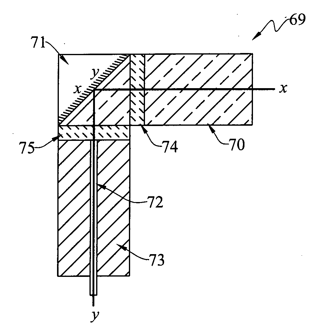
[0086]Referring now to FIG. 4A, a second embodiment of the present invention, generally indicated at 69, comprises an axially non-symmetric short-pitch collimator suitable for use in a fiber optic rotary joint requiring fiber ingress oriented at right angles to the rotation axis of the rotary joint, or for use in applications where size restrictions prevent the use of an axially-symmetric collimator and bending of the fiber to a right angle ingress. The second embodiment is comprised of similar subcomponents to the first general embodiment described in FIG. 3A. Thus, collimator assembly 20 includes a short-pitch gradient-index rod lens 70, a right-angle cube reflector prism 71 (which replaces the glass spacer of the first embodiment), and the fiber / ferrule subassembly comprised of the optical fiber 72 within a ferrule 73. The left end of lens 70 is secured to the right face of prism 71 by means of an optically-transparent epoxy 74. Similarly, the upper end of the fibe...

third embodiment

FIGS. 5A and 5B

[0092]Referring now to FIG. 5A, a third embodiment of the present invention, generally indicated at 76, includes a short-pitch gradient-index rod lens 78, a right-angle triangular reflector prism 79 (which replaces the glass spacer of the first embodiment), and the fiber / ferrule subassembly comprised of the optical fiber 80 within a ferrule 81. The left end of lens 78 is secured to the right face of prism 79 by means of an optically-transparent epoxy 82. Similarly, the upper end of the fiber / ferrule subassembly is affixed to the lower face of prism 79 by means of an optically-transparent epoxy 83. These epoxies can be suitable UV-cured epoxies.

[0093]Referring to FIG. 5B, the cube reflector prism 79 is shown as having an optically-reflective metallic layer 79a on its inclined rear face. Thus, light enters the prism along a central horizontal axis x-x by passing through its vertical right face 32c, and exits through its horizontal lower face 32e along a central vertical...


PUM


Abstract

Fiber optic collimators are disclosed for use in fiber optic rotary joints (20) providing for improvement in insertion loss performance. One embodiment of the fiber optic collimator has a gradient-index rod lens (61) possessing a pitch of less than one-quarter. Improvement in insertion loss arises due to the increase in the effective focal length of the lens as the pitch is reduced, allowing the collimator to achieve a longer working distance. The increase in the effective focal length is accompanied by an increase in the back focal length of the lens, compared to the zero back focal length of the more typical quarter-pitch gradient-index rod lens. The increased back focal length can be filled by a cylindrical glass spacer (64), to which an optical fiber (68) is attached, resulting in a collimator with very similar form factor to the usual quarter-pitch gradient-index rod lens collimator. The increased back focal length can also be filled by a form of right-angle prism (71), to which an optical fiber is attached such that the fiber is oriented at 90 degrees to the optical axis of the lens useful for applications of pancake-style hybrid slip rings wherein the desired direction of fiber ingress to the rotary joint is perpendicular to the rotation axis of the rotary joint.

Description

BACKGROUND ART[0001]A fiber optic rotary joint (“FORJ”) typically has a rotor mounted for rotational movement about an axis relative to a stator. Optical fibers communicate with the rotor and stator, respectively. An optical signal is adapted to be transmitted across the interface between the rotor and stator in either direction; that is, from the rotor to the stator, or vice versa.[0002]There are a number of applications in which a data stream carried in one optical fiber on the transmitting side of the rotary interface is to be transmitted through a collimating lens across that interface, with high signal strength and minimal variation in that signal strength at all relative angular positions between the rotor and stator. Such transmitted data stream may be directed by another collimating lens into another optical fiber on the receiving side of the interface. In some applications, the optical fiber on the transmitting side of the interface is permanently mapped to a particular opt...

Claims


Application Information

Patent Timeline
Patent Type & Authority Applications(United States)
IPC IPC(8): G02B6/40
CPCG02B6/32G02B27/30G02B6/3604G02B6/40
Inventor O'BRIEN, MICHAELSNOW, JAMES
Owner FOCAL TECH
Why Eureka
Try Eureka