Composite Truss Panel Having Fluted Core

a composite truss panel and core technology, applied in the field of composite structures, can solve the problems of difficult use of composite materials for fuel tanks, laminated fluted design, and the need to carry the required compression and shear load, and achieve the effects of reducing weight, buckling, bending, and increasing the overall structural properties of the truss panel

Inactive Publication Date: 2011-12-08
THE BOEING CO
View PDF6 Cites 9 Cited by
  • Summary
  • Abstract
  • Description
  • Claims
  • Application Information

AI Technical Summary

Benefits of technology

The disclosed embodiments provide a composite truss and method for making the same employing a composite sandwich-in-sandwich truss structure (SISTS) in which a composite fluted core is sandwiched between two facesheets and includes integral, lightweight foam stiffeners. The lightweight foam stiffeners employ a low density, high temperature structural foam that increases the overall structural properties of the truss panel, including buckling, bending, impact resistance and insulation. The improved performance of the truss panel may reduce the required number of core flutes and / or facesheet composite plies, thus reducing weight. The use of the high temperature low density foam for both structural load carrying and thermal insulation may permit the use of thinner thermal protection systems (TPS) on the exterior surfaces of the panel. The hollow geometry of the fluted core allows any fuel vapors trapped in the core to be readily purged, and the use of foam adjacent the inner facesheet of the panel may be used to control purge gas temperatures. The SISTS panel structure may allow the use of optimized combinations of high temperature capable polymers and toughened matrix resin systems in a single part to achieve an optimal combination of weight savings, cost reduction, and structural performance. Finally, the use of low density foam in the outer and / or flute walls may permits the various layers of the panel to be thermally isolated.

Problems solved by technology

However, the use of composite materials for fuel tanks is challenging because of the severe environmental conditions to which the components of the tank may be subjected, as well as possible chemical incompatibilities, the cryogenic temperatures of propellants, extreme temperature cycling, long term permeability and requirements for damage tolerance.
Laminated fluted designs had a number of disadvantages, including the need to use relative thick walls in order to carry the required compression and shear loads.
Honeycomb designs may also have various disadvantages, including their relatively heavy weight, and their reduced flatwise tensile strength and shear strength and impact resistance.
Moreover, honeycomb designs rely on core-to-laminate bonds whose quality may not be nondestructively ascertained, and may be more difficult to tailor to particular shapes.
Finally, over time, volatile fuels may permeate through the inner facesheet into the area between the cell walls.
Perforation of the core cell walls in this manner, however, may reduce the shear, compression and bending strength of the panel.

Method used


Image

  • Composite Truss Panel Having Fluted Core
  • Composite Truss Panel Having Fluted Core
  • Composite Truss Panel Having Fluted Core

Examples


Embodiment Construction

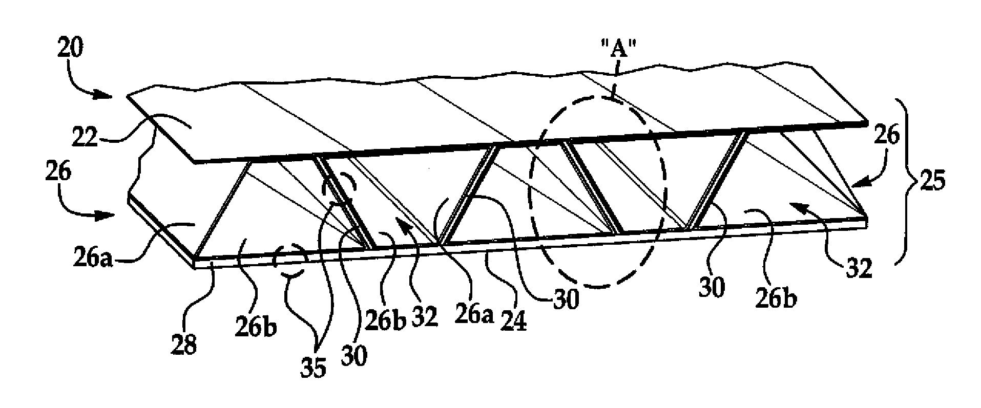
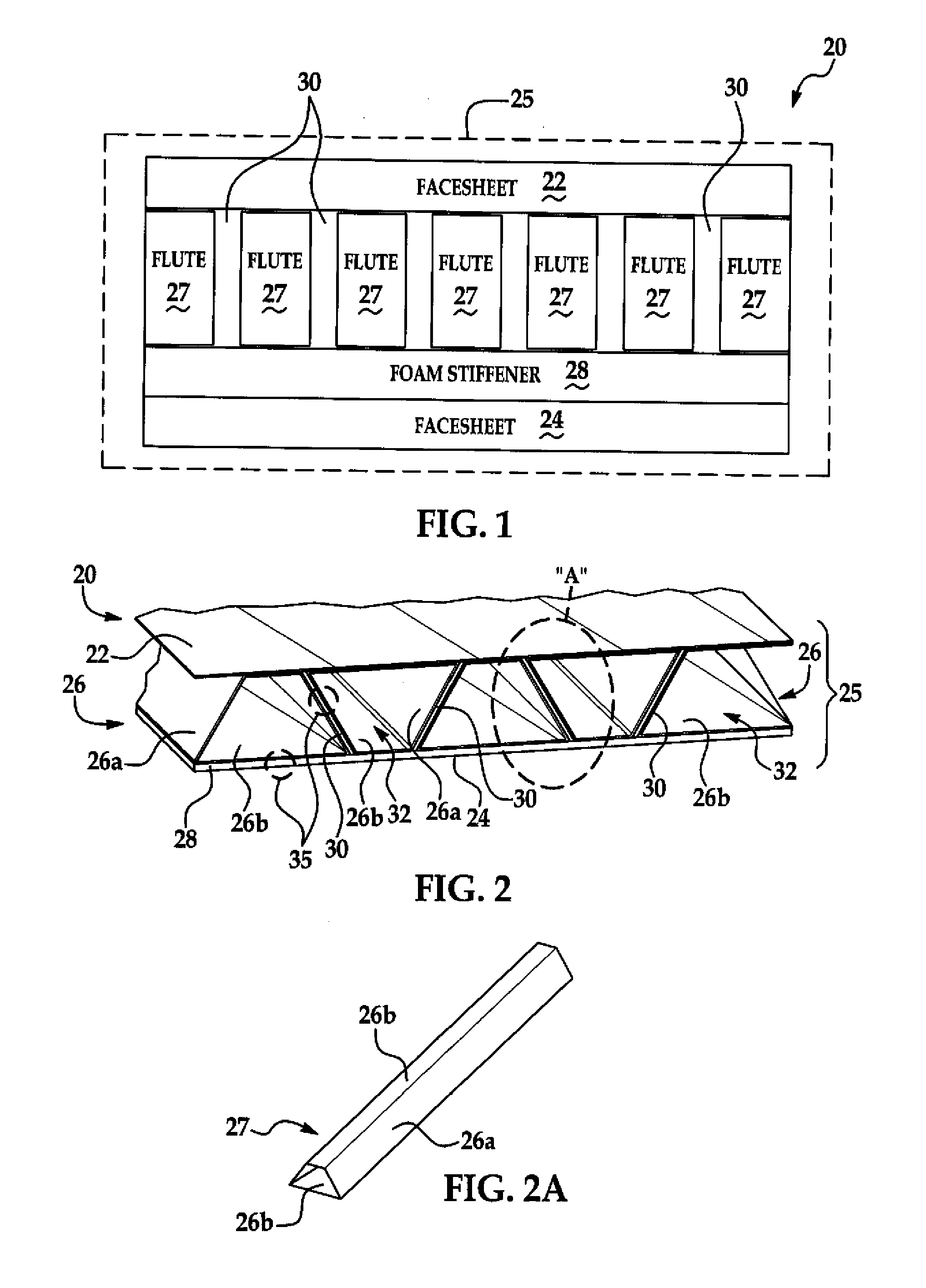
Referring first to FIGS. 1, and 3, the disclosed embodiments generally relate to a composite truss panel 20 which may be used to form a variety of structures such as without limitation, a cryogenic fuel tank (not shown) for aerospace vehicles.

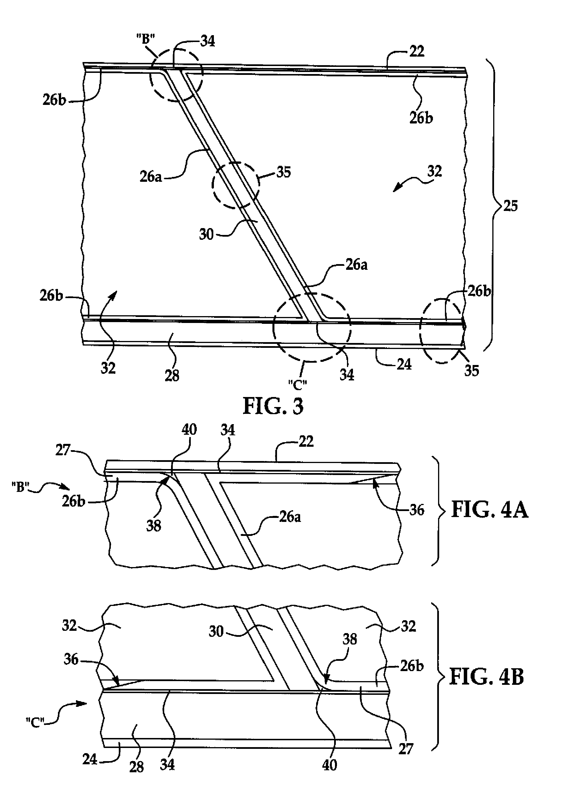
The truss panel 20 broadly comprises a first sandwich 25 that includes a fluted core 26 sandwiched between first and second, generally parallel facesheets 22, 24, and a second sandwich 35. As will be discussed later, in some embodiments, the facesheets 22, 24 may not be parallel to each other. Each of the facesheets 22, 24 may comprise one or more plies of a fiber reinforced resin, such as carbon fiber epoxy. In a cryogenic fuel tank application, facesheet 22 may comprise an inside wall of the tank, while the facesheet 24 forms the outer wall. As will be discussed below in more detail, each of the flutes 27 may also be formed from a fiber reinforced resin material which may comprise one or more plies of a woven or knitted fabric that is cured t...


PUM

PropertyMeasurementUnit
densityaaaaaaaaaa
densityaaaaaaaaaa
densityaaaaaaaaaa

Abstract

A composite truss structure employs a sandwich-in-sandwich construction in which a composite fluted core is sandwiched between two facesheets, and at least one structural foam stiffener is sandwiched within the core or between the facesheets and/or the core.

Description

BACKGROUND INFORMATION1. FieldThis disclosure generally relates to composite structures, and deals more particularly with a sandwich-in-sandwich composite truss panel having a fluted core, as well as a method for making the truss panel.2. BackgroundAerospace vehicles typically require lightweight structural members that maximize payload carrying capacity and mission capabilities. For example, launch and space exploration vehicles often make use of composite materials in areas such as heat shields, nose cones and payload fairings in order to reduce weight while satisfying performance requirements. In order to further reduce vehicle weight, additional components such as cryogenic fuel tanks used to store pressurized propellants may be fabricated from composite materials. However, the use of composite materials for fuel tanks is challenging because of the severe environmental conditions to which the components of the tank may be subjected, as well as possible chemical incompatibilities...

Claims


Application Information

Patent Timeline
Patent Type & Authority Applications(United States)
IPC IPC(8): B32B3/28B32B3/00
CPCB29C70/30B29D24/004B29D99/0014B29K2995/0089B29L2031/7172B32B3/20Y10T156/1025E04C2/34Y10T428/13Y10T428/24661Y10T428/24669Y10T428/24628B32B5/18B32B5/024B32B5/026B32B5/24B32B5/245B32B27/06B32B27/065B32B27/18B32B27/38B32B1/02B32B3/08B32B3/18B32B2260/021B32B2260/046B32B2262/106B32B2266/0214B32B2307/30B32B2307/304B32B2307/50B32B2307/558B32B2307/718B32B2307/72B32B2439/62B32B2605/18
Inventor MCCARVILLE, DOUGLAS A.GUZMAN, JUAN C.HAND, MICHAEL L.ROBINSON, MICHAEL J.
Owner THE BOEING CO
Why Eureka
Try Eureka