Battery tab joint by reaction metallurgy

Active Publication Date: 2011-12-15
GM GLOBAL TECH OPERATIONS LLC
View PDF9 Cites 11 Cited by
  • Summary
  • Abstract
  • Description
  • Claims
  • Application Information

AI Technical Summary

Benefits of technology

[0022]This reactive metallurgy practice is very useful for welding workpieces together. In accordance with this invention, the method is practiced to manage the dimensions of the welded article and to minimize distortion of the members at the welded interface. This may be of particular concern when the workpieces have thicknesses of only a few millimeters or less, for example, battery cell tabs which are typically about 0.2 mm thick. Such dimensional control is accomplished by controlling the amount of workpiece material consumed by the reactive material and discarded as reaction product, as well as controlling the amount of deformation experienced by the workpieces during joining. For the case of very thin material, for example, less than 1 mm thick, where a specific final material thickness is desired, the material could be produced at a greater thickness and then thinned by both the reaction and stress to the desired final thickness.
[0023]The temperature

Problems solved by technology

The joining of metals such as aluminum alloys or copper alloys is complicated by the presence of rapidly forming oxide layers as well as their inherently high electrical and thermal conductivity.
Spot welding can be difficult and requires preparation of the workpiece surface, high currents, high forces, and mechanically well-aligned and stable electrodes.
Short electrode life is common because of reaction between the aluminum workpiece alloy and the copper electrode or welding of the copper workpiece alloy to the copper electrode.
The resultant weld between aluminum workpieces can have high strength, but poor high cycle fatigue performance under some conditions.
Joining the thin tab materials to the much thicker copper conductor is difficult for several reasons.
Second, one of the stack-ups includes a metal combination that is known to form brittle intermetallics, i.e., copper an

Method used


Image

  • Battery tab joint by reaction metallurgy
  • Battery tab joint by reaction metallurgy
  • Battery tab joint by reaction metallurgy

Examples


Embodiment Construction

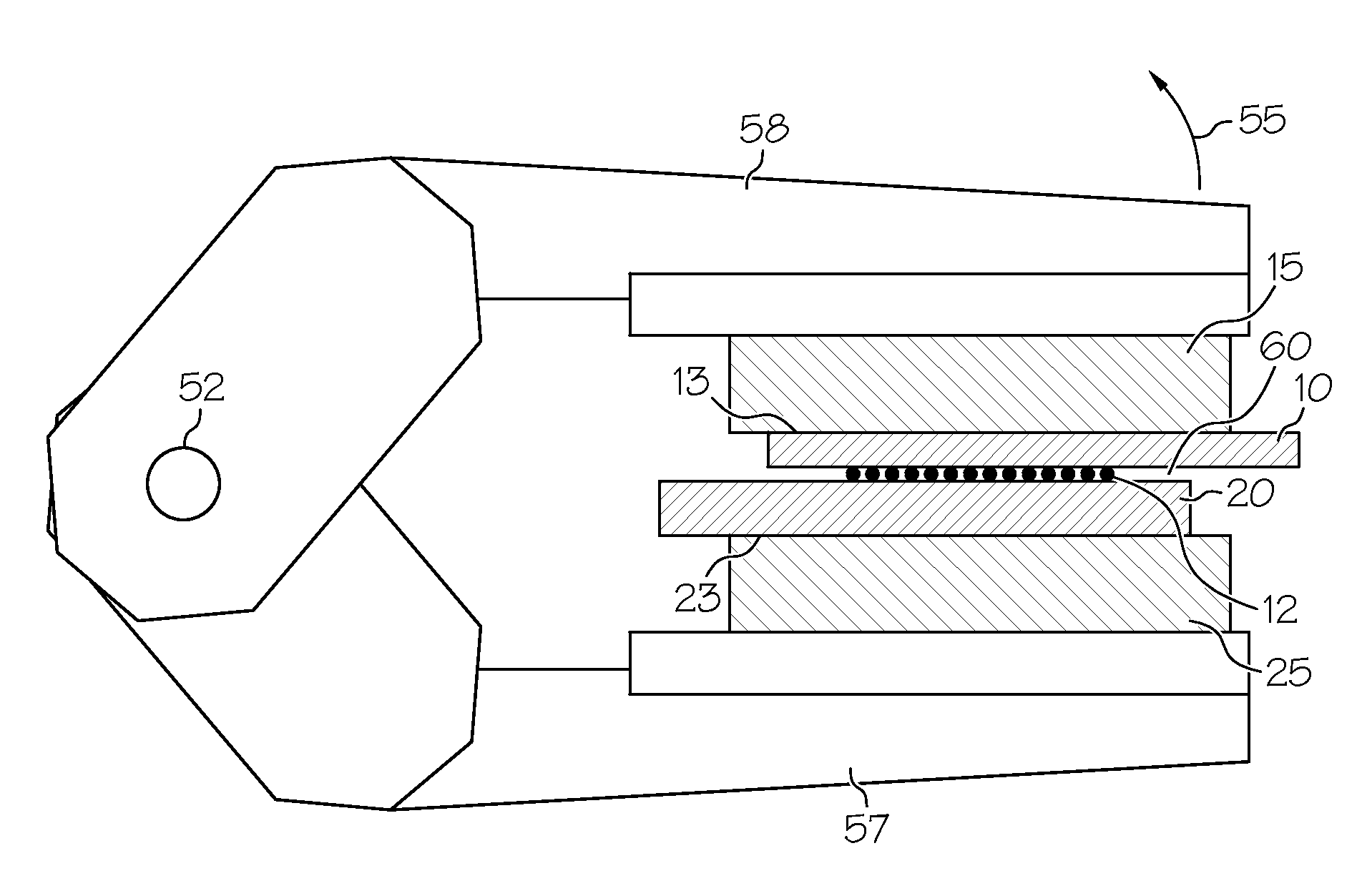
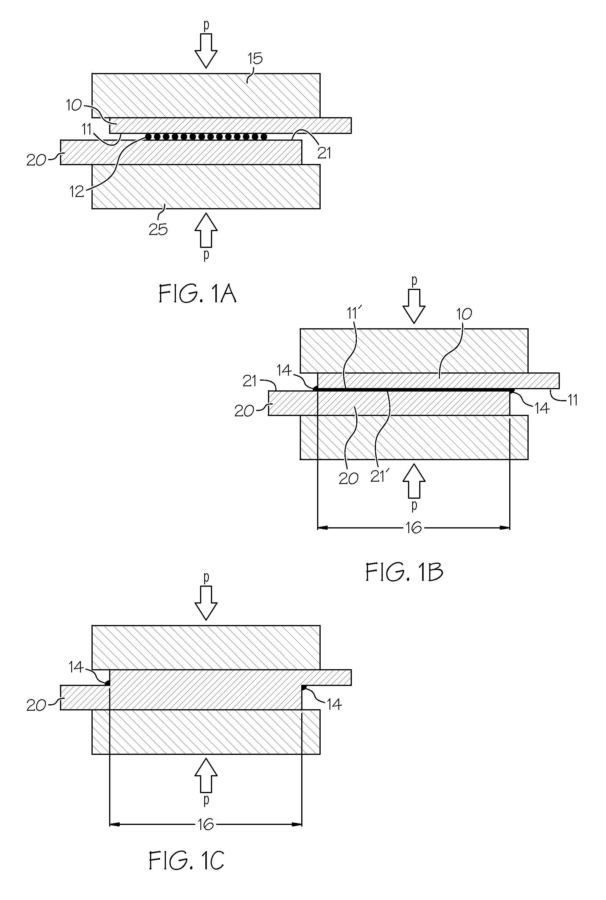
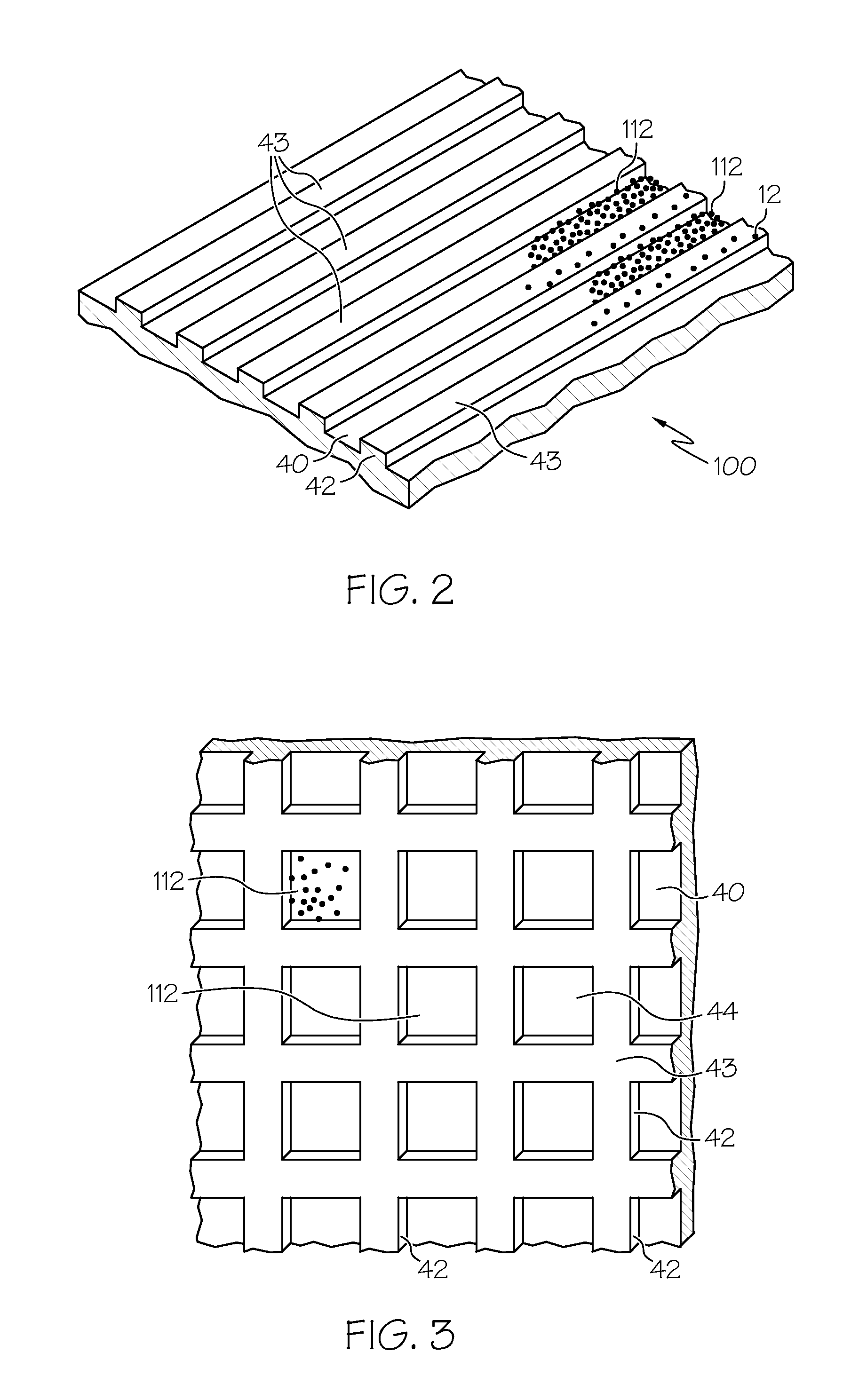
[0036]The invention relates to solid-state welding processes for joining metal or metal alloy workpieces. A reaction product comprising a mobile low-melting temperature liquid-containing material is temporarily formed between joining surfaces. The mobile material is formed as a reaction product between the surfaces to be joined and a preplaced material selected specifically for its ability to react with the base metal alloys. Under the action of an applied force, the reaction product is displaced from the joint and leaves behind cleaned, oxide-free aluminum or copper surfaces that, under continued pressure, form a metal-to-metal bond. The process is practiced to manage consumption and deformation of the facing surfaces of the workpieces.

[0037]In many embodiments of this invention, the process may be used to form solid-state welded interfaces between copper metal or alloy or aluminum metal or alloy workpieces and other copper metal or alloy or aluminum metal or alloy workpieces. Exam...


PUM

PropertyMeasurementUnit
Temperatureaaaaaaaaaa
Thicknessaaaaaaaaaa
Pressureaaaaaaaaaa

Abstract

Copper metal or metal alloy workpieces and/or aluminum metal or metal alloy workpieces are joined in a solid state weld by use of a reactive material placed, in a suitable form, at the joining surfaces. Joining surfaces of the workpieces are pressed against the interposed reactive material and heated. The reactive material alloys or reacts with the workpiece surfaces consuming some of the surface material in forming a liquid-containing reaction product comprising a low melting liquid that removes oxide films and other surface impediments to a welded bond across the interface. Further pressure is applied to expel the reaction product and to join the workpiece surfaces in a solid state weld bond.

Description

STATEMENT OF RELATED CASES[0001]This application related to U.S. application Ser. No. 12 / 420,927, entitled Welding Light Metal Workpieces by Reaction Metallurgy, filed Apr. 9, 2009, which is incorporated herein by reference.TECHNICAL FIELD[0002]This invention relates generally to welding processes, and more particularly to solid-state welding processes for joining workpieces of metal or metal alloys such as aluminum metal or alloys or copper metal or alloys.BACKGROUND OF THE INVENTION[0003]The joining of metals such as aluminum alloys or copper alloys is complicated by the presence of rapidly forming oxide layers as well as their inherently high electrical and thermal conductivity. Spot welding can be difficult and requires preparation of the workpiece surface, high currents, high forces, and mechanically well-aligned and stable electrodes. Short electrode life is common because of reaction between the aluminum workpiece alloy and the copper electrode or welding of the copper workpi...

Claims


Application Information

Patent Timeline
IPC IPC(8): B23K31/02
CPCY10T428/12903B23K2203/12B23K20/021B23K2203/10Y10T428/12736B23K20/16B23K2103/10B23K2103/12
Inventor SIGLER, DAVID R.SCHROTH, JAMES G.
Owner GM GLOBAL TECH OPERATIONS LLC
Why Eureka
Try Eureka