Image-forming lens, and imaging apparatus and information device using the image-forming lens
a technology of image-forming lens and image-forming lens, which is applied in the field of image-forming lens and imaging apparatus and information device using the image-forming lens, can solve the problems of large asymmetry of refractive power arrangement, large length of lens, so as to reduce astigmatism and field curvature, and high performance
- Summary
- Abstract
- Description
- Claims
- Application Information
AI Technical Summary
Benefits of technology
Problems solved by technology
Method used
Image
Examples
example 1
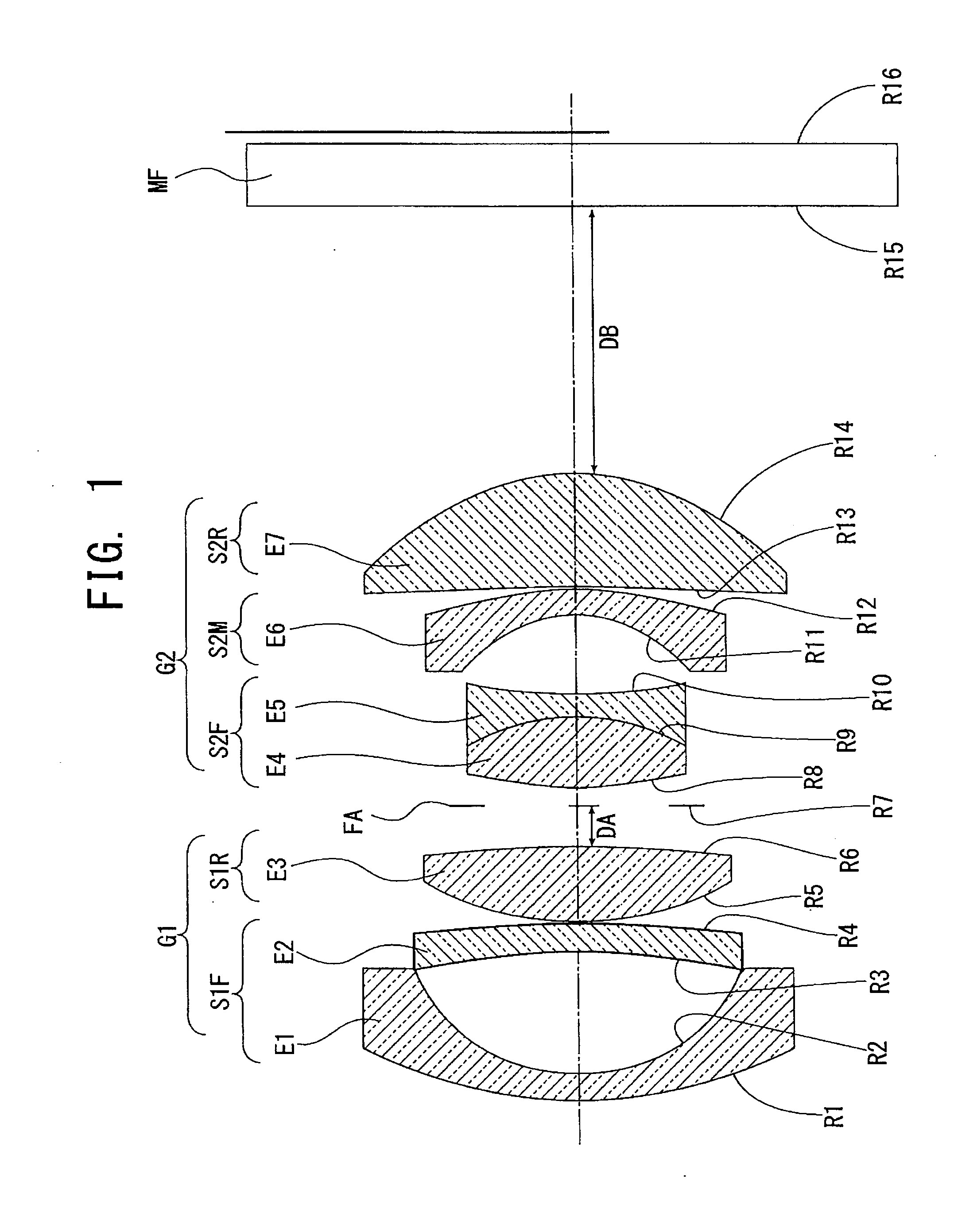
[0125]Next, specific examples will be explained based on the embodiment of the present invention as described above.
[0126]The following Examples 1 to 6 are examples of specific configurations by specific numerical value examples of image-forming lenses according to the present invention. And Example 7 is a specific example of an imaging apparatus or information device according to the embodiment of the present invention using a lens unit having a zoom lens described in the Examples 1 to 6 as an imaging optical system.
[0127]The Examples 1 to 6 describe configurations and specific numerical value examples of each image-forming lens.
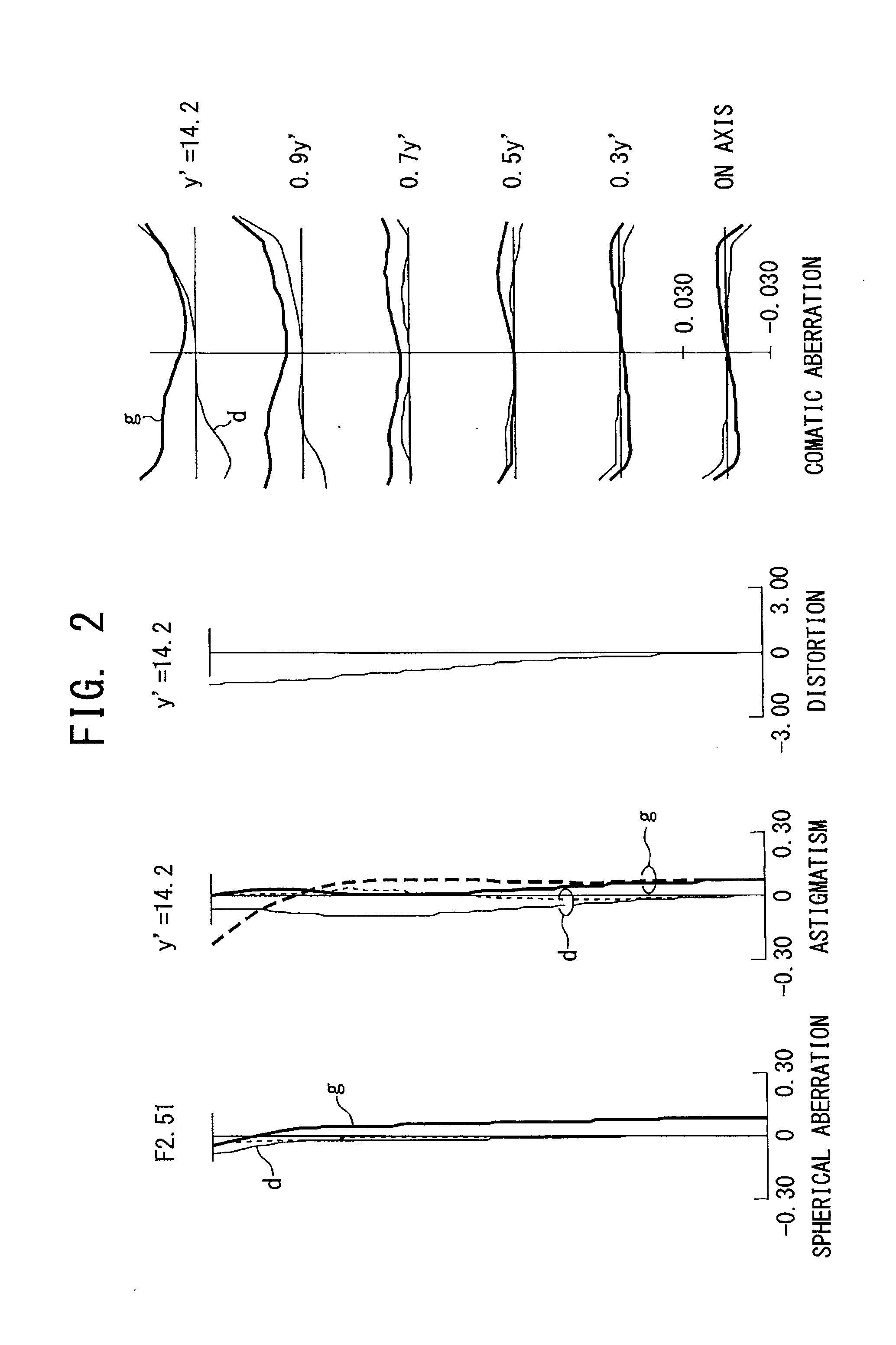
[0128]In each of the Examples 1 to 6, a maximum image height is 14.2 mm.
[0129]In the Examples 1 to 6, as an optical element of a parallel plate placed on an image plane side of the second lens group, an optical filter such as an optical low-pass filter, an infrared cut filter, or the like, or a cover glass (seal glass) of a light-receiving element of a CMOS...
example 2
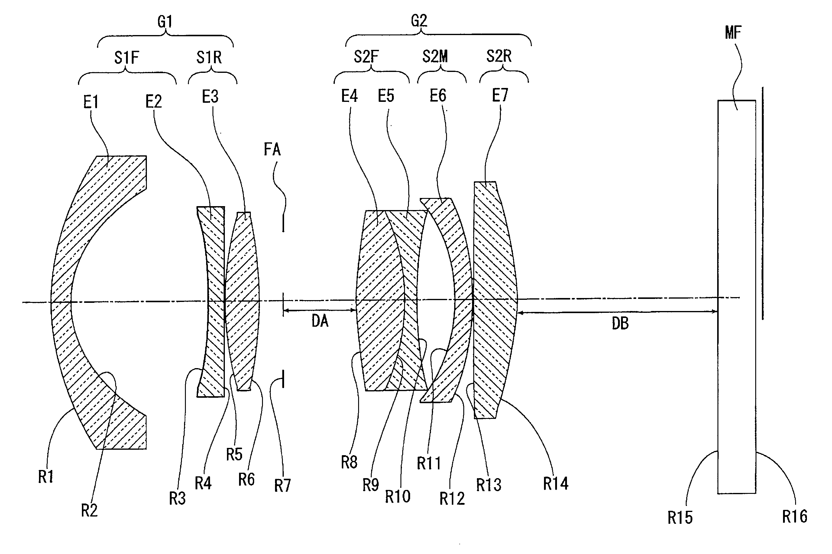
[0206]FIG. 4 is a schematic vertical cross-sectional diagram illustrating a constitution of an optical system of an image-forming lens according to Example 2 of the present invention.
[0207]The image-forming lens illustrated in FIG. 4 has a first lens E1, a second lens E2, a third lens E3, a fourth lens E4, a fifth lens E5, a sixth lens E6, a seventh lens E7, an aperture FA, and a filter MF.
[0208]In this case, the first lens E1, the second lens E2, and the third lens E3 constitute a first lens group G1, which is placed on an object side from the aperture FA. The fourth lens E4, the fifth lens E5, the sixth lens E6, and the seventh lens E7 constitute a second lens group G2, which is placed on an image plane (image) side from the aperture FA. Each of the lens groups is supported by a common supporting frame and so on per group, and in a case of focusing and the like, each lens group moves integrally.
[0209]In this case, the aperture FA moves integrally with the first lens group G1.
[0210...
example 3
[0256]FIG. 7 is a schematic vertical cross-sectional diagram illustrating a constitution of an optical system of an image-forming lens according to Example 3 of the present invention.
[0257]The image-forming lens illustrated in FIG. 7 has a first lens E1, a second lens E2, a third lens E3, a fourth lens E4, a fifth lens E5, a sixth lens E6, a seventh lens E7, an eighth lens E8, an aperture FA, and a filter MF.
[0258]The first lens E1, the second lens E2, the third lens E3, and the fourth lens E4 constitute a first lens group G1, which is placed on an object side from the aperture FA. The fifth lens E5, the sixth lens E6, the seventh lens E7, and the eighth lens E8 constitute a second lens group G2, which is placed on an image plane (image) side from the aperture FA. Each of the lens groups is supported by a common supporting frame and so on per group, and in a case of focusing and the like, each lens group moves integrally.
[0259]In this case, the aperture FA moves integrally with the ...
PUM
 Abstract
Description
Claims
Application Information
 - R&D
- Intellectual Property
- Life Sciences
- Materials
- Tech Scout
- Unparalleled Data Quality
- Higher Quality Content
- 60% Fewer Hallucinations
Browse by: Latest US Patents, China's latest patents, Technical Efficacy Thesaurus, Application Domain, Technology Topic, Popular Technical Reports.
© 2025 PatSnap. All rights reserved.Legal|Privacy policy|Modern Slavery Act Transparency Statement|Sitemap|About US| Contact US: help@patsnap.com


