
Vehicle air-conditioning system

a technology for air-conditioning systems and electric vehicles, which is applied in the operation mode of machines, domestic cooling devices, lighting and heating devices, etc., can solve the problems of inability to establish a heating system using only exhaust heat as a heat source, the amount of exhaust heat is so small, and the air-conditioning system used in electric vehicles cannot perform a heating operation. achieve the effect of simplifying the circuit configuration, reducing the number of components, and high capacity

Active Publication Date: 2012-01-19
MITSUBISHI HEAVY IND LTD
View PDF25 Cites 48 Cited by
  • Summary
  • Abstract
  • Description
  • Claims
  • Application Information

AI Technical Summary

Benefits of technology

[0045]According to the present invention, for cooling, a cooling operation can be performed using a cooling cycle in which the first refrigerant condenser is used as a condenser, and the first refrigerant evaporator of the HVAC unit is used as an evaporator; in a situation where a dehumidifying operation is needed, such as intermediate seasons, a dehumidifying operation can be performed using a dehumidifying cycle in which the second refrigerant condenser of the HVAC unit is used as a condenser, and the first refrigerant evaporator is used as an evaporator; and for heating, a high-efficiency, high-capacity heating operation using ventilation exhaust heat as a heat source can be performed using a heating cycle in which the second refrigerant condenser of the HVAC unit is used as a condenser, and the second refrigerant evaporator for recovering exhaust heat disposed in the ventilation channel is used as an evaporator. Accordingly, this can simplify the circuit configuration and considerably reduce the number of components to make the system compact as compared with a system equipped with an exhaust heat recovery cycle in a separate system, thus improving the ease of installation in vehicles and reducing the cost. Furthermore, unlike a heat pump that absorbs heat from outside air, the need for a defrosting operation of the first refrigerant condenser disposed outside the vehicle interior at a low outside air temperature can be nearly eliminated, which can increase the heating efficiency and prevent an operation using the evaporator installed outside the vehicle interior, which stabilizes the evaporation action of the evaporator, thus eliminating the need to install an accumulator and intake-refrigerant pressure detecting means, which makes the system compact and achieves a low cost. Furthermore, in a situation where a dehumidifying operation is needed, such as in intermediate seasons, a dehumidifying operation using the heat pump cycle can also be achieved.

Problems solved by technology

Air-conditioning systems used in electric vehicles cannot perform a heating operation using combustion exhaust heat from engine cooling water etc. because they are not equipped with an engine.
Although exhaust heat from a driving motor, a battery, etc. substituting for an engine can be used, the amount of exhaust heat is so small that a heating system using only exhaust heat as a heat source cannot be established.
On the other hand, although a heating system using an electric heater is conceivable, this has the problem of significantly decreasing the driving mileage of the vehicle because power consumption for heating is large relative to the battery capacity.
However, a reverse-cycle heat pump in which a refrigerant circuit is switched to use a condenser as an evaporator and an evaporator as a condenser during heating has some problems: at a low outside air temperature, the condenser, which is installed outside the vehicle interior, needs a defrosting operation (during heating, it functions as an evaporator), the heating capacity is insufficient, a dehumidifying operation is impossible, windows fog up when switching between cooling and heating, and so on.
Furthermore, with the foregoing reverse-cycle heat pump, in the case of a heating operation under low outside air temperature conditions, the refrigerant evaporation action of the evaporator (which functions as a condenser during cooling) installed outside the vehicle interior changes considerably, which may cause a liquid slugging operation when starting up or an abnormal low pressure operation, exerting an excessive load on the compressor, thus causing damage to the compressor.
To prevent the occurrence of such situations, an accumulator or intake-refrigerant pressure detecting means is disposed at the intake side of the compressor; however, this has the problems of complicating the system and increasing the cost.

Method used


Image

  • Vehicle air-conditioning system
  • Vehicle air-conditioning system
  • Vehicle air-conditioning system

Examples


first embodiment

[0058]A first embodiment of the present invention will be described hereinbelow using FIG. 1.

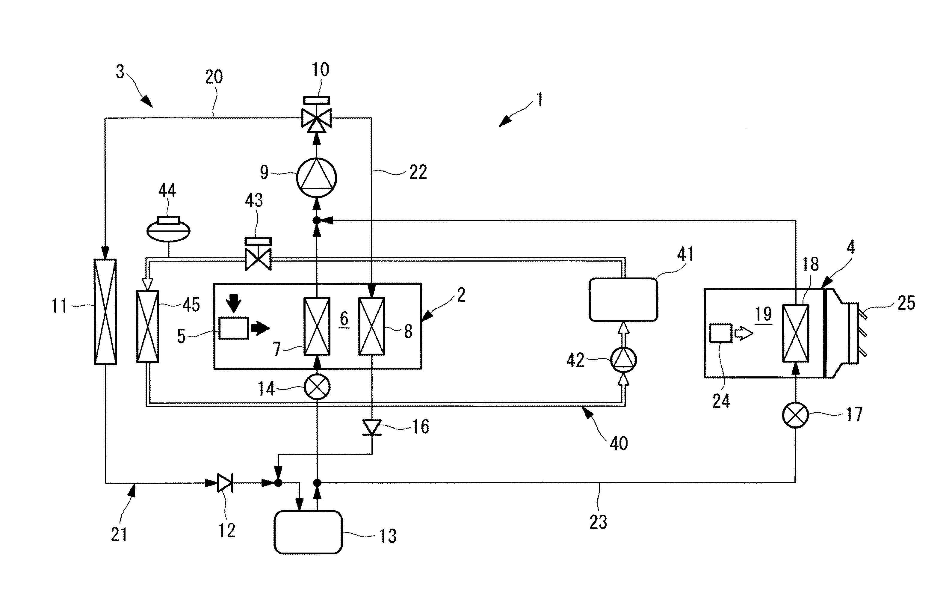
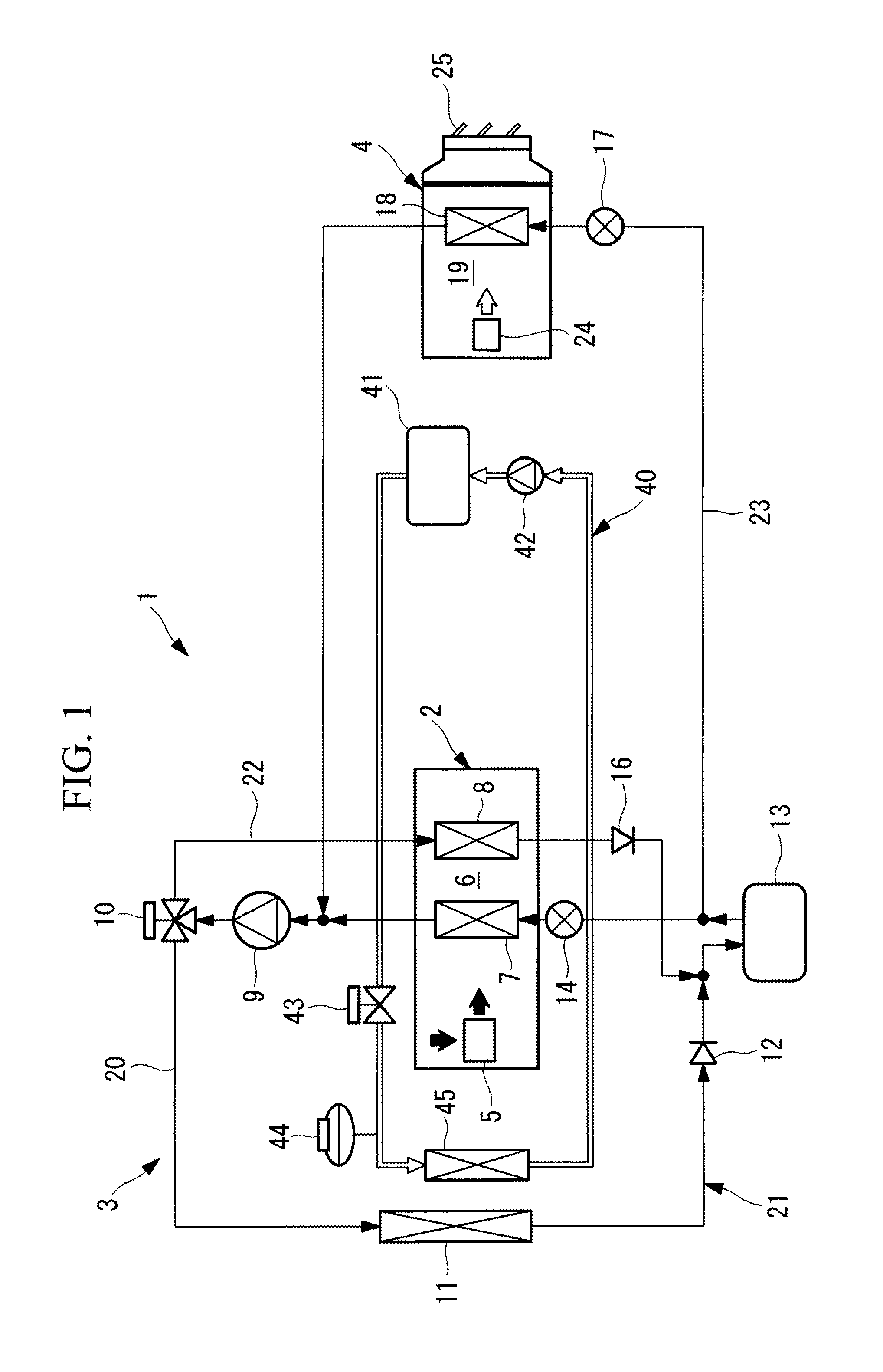
[0059]FIG. 1 shows a configuration diagram of a vehicle air-conditioning system 1 according to a first embodiment of the present invention.

[0060]The vehicle air-conditioning system 1 of this embodiment is equipped with a heating ventilation and air conditioning unit (HVAC unit) 2, a heat pump cycle 3, and a ventilation-exhaust-heat recovery unit 4.

[0061]The HVAC unit 2 includes a blower 5 that introduces inside air from a vehicle interior, outside air, or a mixture of inside air and outside air by switching to any one of these and blows it downstream and a first refrigerant evaporator 7 and a second refrigerant condenser 8 which are disposed in sequence from the upstream side to the downstream side in an air channel 6 that continues from the blower 5. This HVAC unit 2 is generally disposed in an instrument panel at the front of the vehicle interior and is configured to blow out an airflow wh...

second embodiment

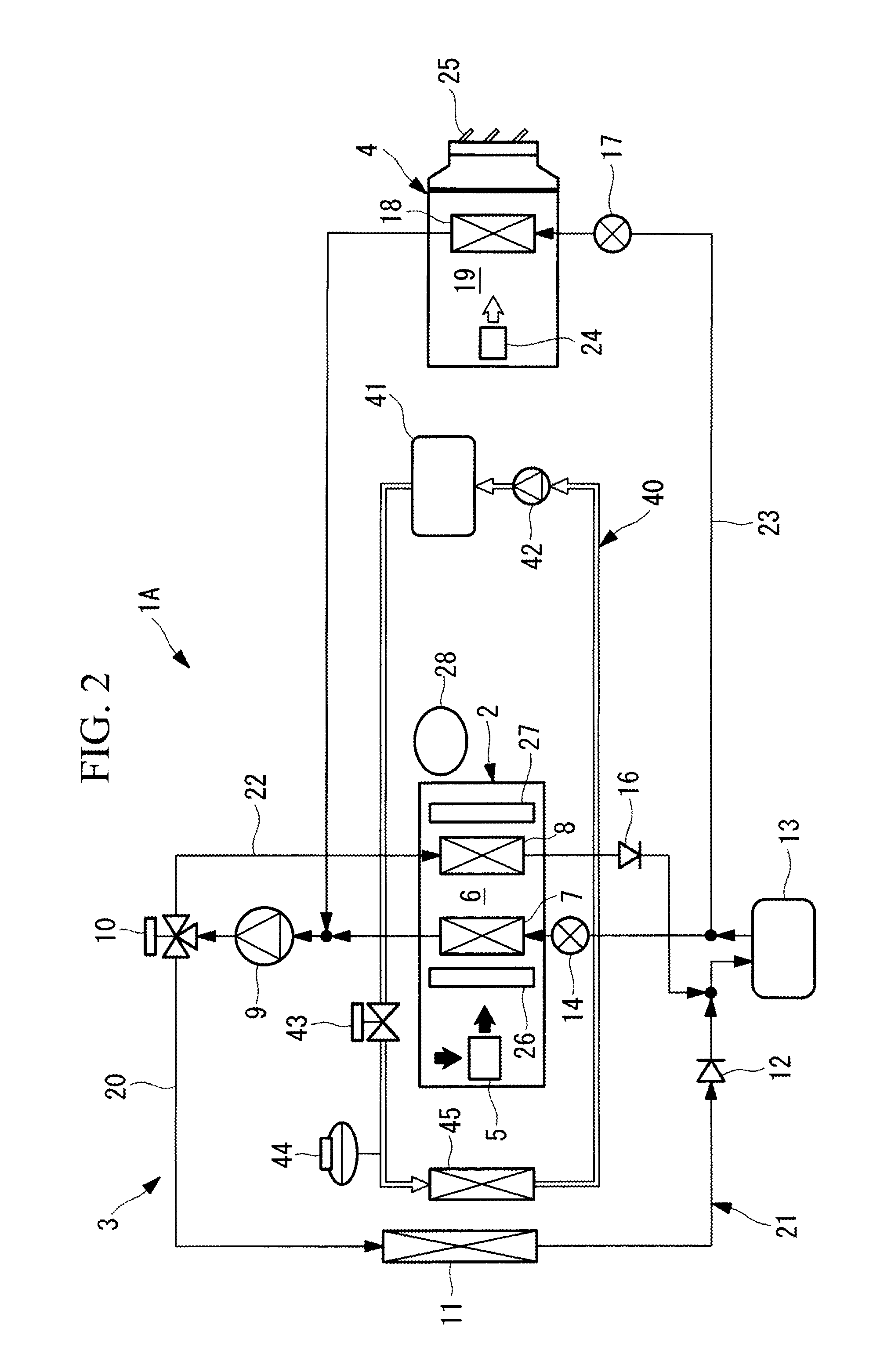
[0076]Next, a second embodiment of the present invention will be described using FIG. 2.

[0077]A vehicle air-conditioning system 1A of this embodiment differs from the foregoing vehicle air-conditioning system 1 of the first embodiment in that PTC heaters 26 and 27 and a humidity sensor 28 are provided. Since the other features are the same as those of the vehicle air-conditioning system 1 of the first embodiment, descriptions thereof will be omitted.

[0078]In the vehicle air-conditioning system 1A of this embodiment, as shown in FIG. 2, the HVAC unit 2 is configured such that the PTC heater (Positive Temperature Coefficient Heater) 26 is disposed upstream of the refrigerant evaporator 7 and the PTC heater 27 is disposed downstream of the second refrigerant condenser 8 in the air channel 6. Furthermore, the humidity sensor 28 is provided in the vehicle interior for sensing window fogging.

[0079]As described above, by disposing the PTC heaters 26 and 27 in the air channel 6 of the HVAC ...

third embodiment

[0083]Next, a third embodiment of the present invention will be described using FIG. 3.

[0084]A vehicle air-conditioning system 1B of this embodiment differs from the vehicle air-conditioning systems 1 and 1A of the foregoing first and second embodiments in that the PTC heater 29 is provided in the ventilation channel 19. Since the other features are the same as those of the vehicle air-conditioning systems 1 and 1A of the first and second embodiments, descriptions thereof will be omitted.

[0085]As shown in FIG. 3, the vehicle air-conditioning system 1B of this embodiment is configured such that the PTC heater 29 is provided upstream of the second refrigerant evaporator 18 in the ventilation channel 19 of the ventilation-exhaust-heat recovery unit 4. This embodiment is the same as the second embodiment in that the PTC heater 27 is provided downstream of the second refrigerant condenser 8 in the HVAC unit 2, and the humidity sensor 28 for sensing window fogging is provided in the vehic...


PUM


Abstract

A vehicle air-conditioning system (1) includes an HVAC unit (2) in which a first refrigerant evaporator (6) and a second refrigerant condenser (7) are disposed in an air channel (5) communicating with a vehicle interior space; and a heat pump cycle (3) in which a refrigerant compressor (8), a refrigerant switching device (9), a first refrigerant condenser (10) that exchanges heat with the outside air, a first expansion valve (13), and a first refrigerant evaporator (6) are connected in sequence and in which the second refrigerant condenser (7) is connected in parallel with the first refrigerant condenser (10) via the refrigerant switching device (9). An exhaust-heat recovery circuit (21) equipped with a second refrigerant evaporator (16) disposed in a ventilation channel (17) from the vehicle interior and a second expansion valve (15) is connected in parallel with the first expansion valve (13) and the first refrigerant evaporator (6) of the heat pump cycle (3).

Description

TECHNICAL FIELD[0001]The present invention relates to a vehicle air-conditioning system suitable for air conditioning of electric vehicles, etc.BACKGROUND ART[0002]Air-conditioning systems used in electric vehicles cannot perform a heating operation using combustion exhaust heat from engine cooling water etc. because they are not equipped with an engine. Although exhaust heat from a driving motor, a battery, etc. substituting for an engine can be used, the amount of exhaust heat is so small that a heating system using only exhaust heat as a heat source cannot be established. On the other hand, although a heating system using an electric heater is conceivable, this has the problem of significantly decreasing the driving mileage of the vehicle because power consumption for heating is large relative to the battery capacity.[0003]Thus, a heat pump system equipped with an electric compressor has been considered as an air-conditioning system for electric vehicles. However, a reverse-cycle...

Claims


Application Information

Patent Timeline
IPC IPC(8): F25B29/00F25B49/00F25B49/02
CPCB60H1/2225B60H1/3204B60H1/22F25B5/02F25B2400/16B60H1/3213B60H1/039
Inventor KONDO, TOSHIHISANAKAGAWA, NOBUYASUETAKE, HIDEKIMORISHITA, MASATOSHI
Owner MITSUBISHI HEAVY IND LTD
Features
  • Generate Ideas
  • Intellectual Property
  • Life Sciences
  • Materials
  • Tech Scout
  • Unparalleled Data Quality
  • Higher Quality Content
  • 60% Fewer Hallucinations
Learn More