Wideband balun having a single primary and multiple secondaries

a wideband balun and primary technology, applied in the field of wideband transmitters, can solve the problems of undetectable two-path transmitter circuit of fig. 4 as implemented, reduce the quality factor (q) of the balun, and reduce the power consumption

Active Publication Date: 2012-01-19
QUALCOMM INC
View PDF4 Cites 57 Cited by
  • Summary
  • Abstract
  • Description
  • Claims
  • Application Information

AI Technical Summary

Benefits of technology

[0009]An RF transmitter capable of transmitting over a wide range of frequencies includes a mixer, a wideband high-Q balun, a first driver amplifier and a second driver amplifier. The wideband high-Q balun has a single primary winding and two secondary windings. A differential output of the mixer is coupled to the primary winding. A first of the two secondary windings is coupled to drive the first driver amplifier in single-ended fashion. A second of the two secondary windings is coupled to drive the second driver amplifier in single-ended fashion. One driver amplifier is used when transmitting at lower frequencies whereas the other driver amplifier is used when transmitting at higher frequencies. By appropriate sizing of the inductances of the secondary windings and by switching out one of the secondary windings at certain times, the balun is tunable to operate over the wide range of frequencies while having a high quality factor Q, thereby facilitating reduced power consumption in the mixer / balun circuit while simultaneously meeting performance requirements.

Problems solved by technology

Unfortunately, making the first and second capacitors large and programmable in this way reduces the quality factor (the “Q”) of the balun.
Due in part to this low quality factor, the transceiver when transmitting in the low band may emit an undesirable amount of receive band noise in a nearby receive band even though the transmitter is tuned to transmit in a transmit band.
The two-path transmitter circuit of FIG. 4 does not have the low Q balun problem of the transmitter circuit of FIG. 2, but the two-path transmitter circuit of FIG. 4 is undesirably large as implemented due to the redundant circuitry.
The two-path transmitter also consumes an undesirably large amount of power.
Such long interconnections often result in increased current consumption.

Method used


Image

  • Wideband balun having a single primary and multiple secondaries
  • Wideband balun having a single primary and multiple secondaries
  • Wideband balun having a single primary and multiple secondaries

Examples


Embodiment Construction

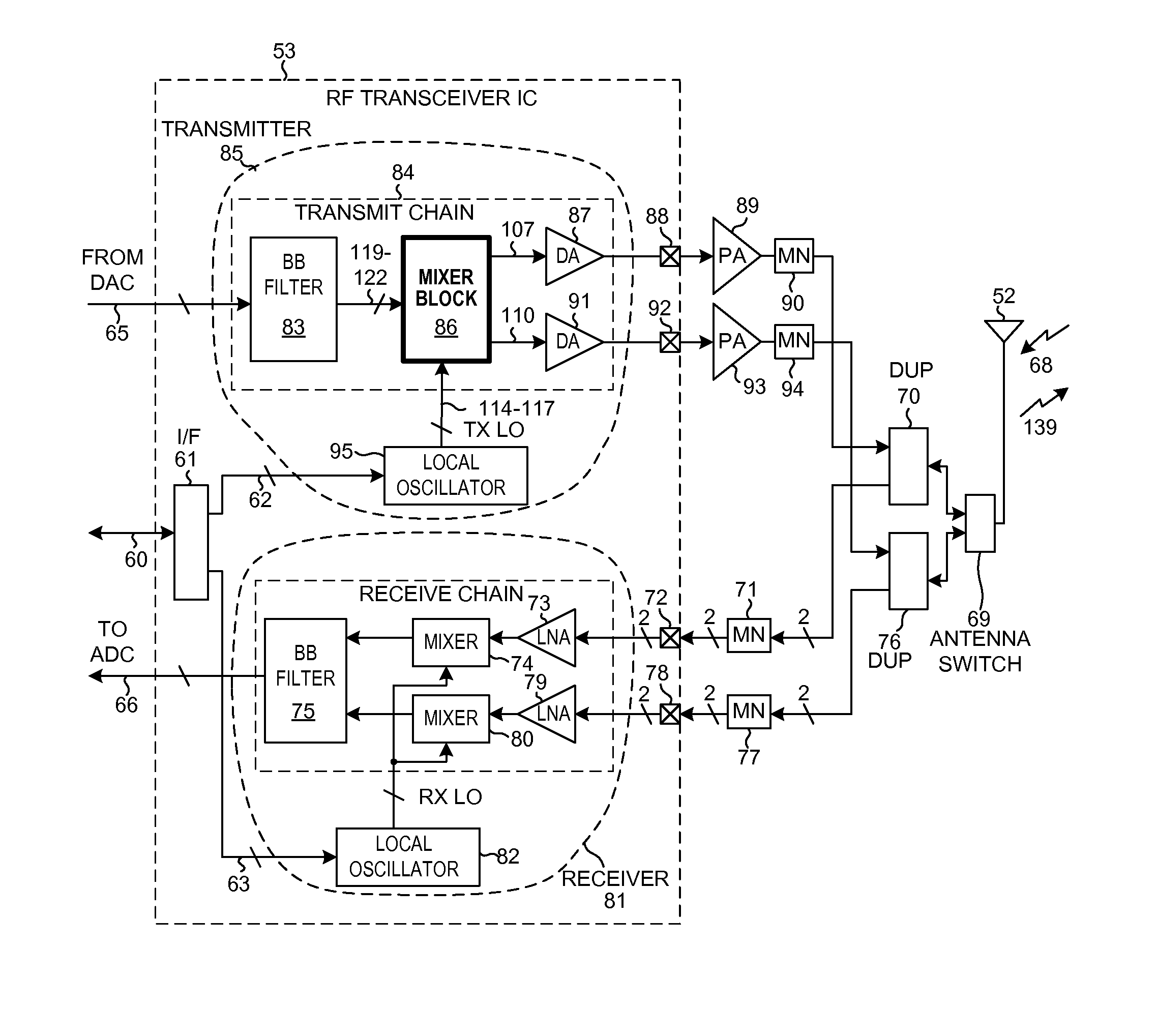
[0027]FIG. 5 is a diagram of a mobile communication device 51 that includes a mixer / balun circuit in accordance with one novel aspect. In this example, mobile communication device 51 is a multi-band cellular telephone handset. Device 51 includes (among other parts not illustrated) an antenna 52 usable for receiving and transmitting cellular telephone communications, an RF (Radio Frequency) transceiver integrated circuit 53, and a digital baseband processor integrated circuit 54. In some examples, the transceiver circuitry and the digital baseband circuitry are implemented on the same integrated circuit, but a two integrated circuit implementation is set forth here for illustration purposes.

[0028]Digital baseband integrated circuit 54 includes a processor 55 that executes a program 56 of processor-executable instructions. Program 56 is stored in a processor-readable medium 57 that in this case is a semiconductor memory. Processor 55 accesses memory 57 via local bus 58. Processor 55 i...


PUM


Abstract

An RF transmitter capable of transmitting over a wide range of frequencies includes a mixer, a wideband high-Q balun, a first driver amplifier and a second driver amplifier. The balun has a single primary winding and two secondary windings. A differential output of the mixer is coupled to the primary winding. A first of the two secondary windings is coupled to drive the first driver amplifier. A second of the two secondary windings is coupled to drive the second driver amplifier. One driver amplifier is used when transmitting at lower frequencies whereas the other driver amplifier is used when transmitting at higher frequencies. By appropriate sizing of the inductances of the secondary windings and by switching out one of the secondary windings at certain times, the balun is tunable to operate over the wide frequency range while having a high quality factor Q, thereby facilitating reduced power consumption while simultaneously meeting performance requirements.

Description

BACKGROUND INFORMATION[0001]1. Technical Field[0002]The present disclosure relates to wideband transmitters, and more particularly to mixers and baluns used in wideband transmitters.[0003]2. Background Information[0004]Many types of RF (Radio Frequency) transceivers, including cellular telephone transceivers such as in multi-band cellular telephones, must work over a wide frequency range. In one example, a cellular telephone may be required to operate in a first frequency band referred to here as a “cell band” or a “low band”. The same cellular telephone may also be required to operate in a second frequency band referred to here as a “PCS band” or a “mid band”. FIG. 1 (Prior Art) is a diagram that shows frequency along the horizontal axis. Low band 1 in this example extends from 824 MHz to 915 MHz and mid band 2 extends from 1710 MHz to 1980 MHz.[0005]FIG. 2 (Prior Art) is a circuit diagram that illustrates a first way that a transmitter of a multi-band cellular telephone transceive...

Claims


Application Information

Patent Timeline
Patent Type & Authority Applications(United States)
IPC IPC(8): G06G7/12
CPCH03H7/422H03H7/465H03D7/1441H03H7/1775H03D7/165H03D2200/0023H03D7/1458
Inventor SANKARANARAYANAN, JANAKIRAM G.ASURI, BHUSHAN S.PANIKKATH, VINOD V.YAN, HONGYANKHATRI, HIMANSHUBHAGAT, MAULIN
Owner QUALCOMM INC
Why Eureka
Try Eureka