Expander for Stirling Engines and Cryogenic Coolers

a technology for stirling engines and coolers, which is applied in special engines, refrigeration machines, gas cycle refrigeration machines, etc., can solve the problems of limiting the ability to miniaturize the overall cryogenic cooler, and achieve the effects of reducing heat conduction loss

Inactive Publication Date: 2012-01-26
TELEDYNE FLIR LLC
View PDF11 Cites 15 Cited by
  • Summary
  • Abstract
  • Description
  • Claims
  • Application Information

AI Technical Summary

Benefits of technology

[0010]Unlike the common displacer which acts as an expander piston and regenerator, the inventive displacer serves only one purpose and it is to perform gas expansion operation and gas displacement. It does not have to contain within it the regenerator and thus its geometry and mechanical structure can take any shape and be optimized for maximum thermal insulation and mechanical flexibility / self alignment with cylinder bore with lower thermal conduction to minimize heat conduction loss along the displacer. In one embodiment, the displacer can be a stiff hollow cylinder with a closed end proximate to the coldwell and made from a low thermal conductive, engineered plastic. In another embodiment, the displacer can have a piston head proximate to the coldwell and a thin shaft or rod, which has a small diameter to minimize heat conduction loss. The thin shaft may have a flexural modulus that allows the displacer to self-correct to minimize frictional contacts with the cold finger which can generate heat.
[0011]The invention is also directed to a cold finger that has a thermal effective length that is substantially longer than its physical or geometrical length. In one embodiment, the cold finger comprises a plurality of tubes that are arranged in a concentric arrangement and are connected selectively to form a serpentine thermal path to reduce heat conduction loss. Stiffeners can be used with the plurality of tubes to enhance the structural integrity or stiffness of the cold finger.

Problems solved by technology

One major challenge when attempting to reduce expander length is the need to maintain a predetermined surface area for a given mass flow rate and cooling capacity by the regenerator matrix.
It is a challenge to minimize the length of the expander while maintaining efficient thermal exchange, i.e., adequate regenerator surface area, minimum pressure drop, large axial thermal resistance along the regenerator, large thermal capacitance and minimum weight.
Satisfying these design constraints has resulted in a relatively long expander assembly length LE and thus limits the ability to miniaturize the overall cryogenic cooler.

Method used


Image

  • Expander for Stirling Engines and Cryogenic Coolers
  • Expander for Stirling Engines and Cryogenic Coolers
  • Expander for Stirling Engines and Cryogenic Coolers

Examples


Embodiment Construction

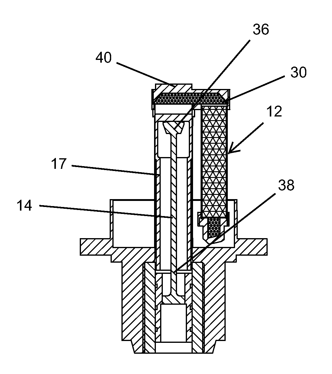
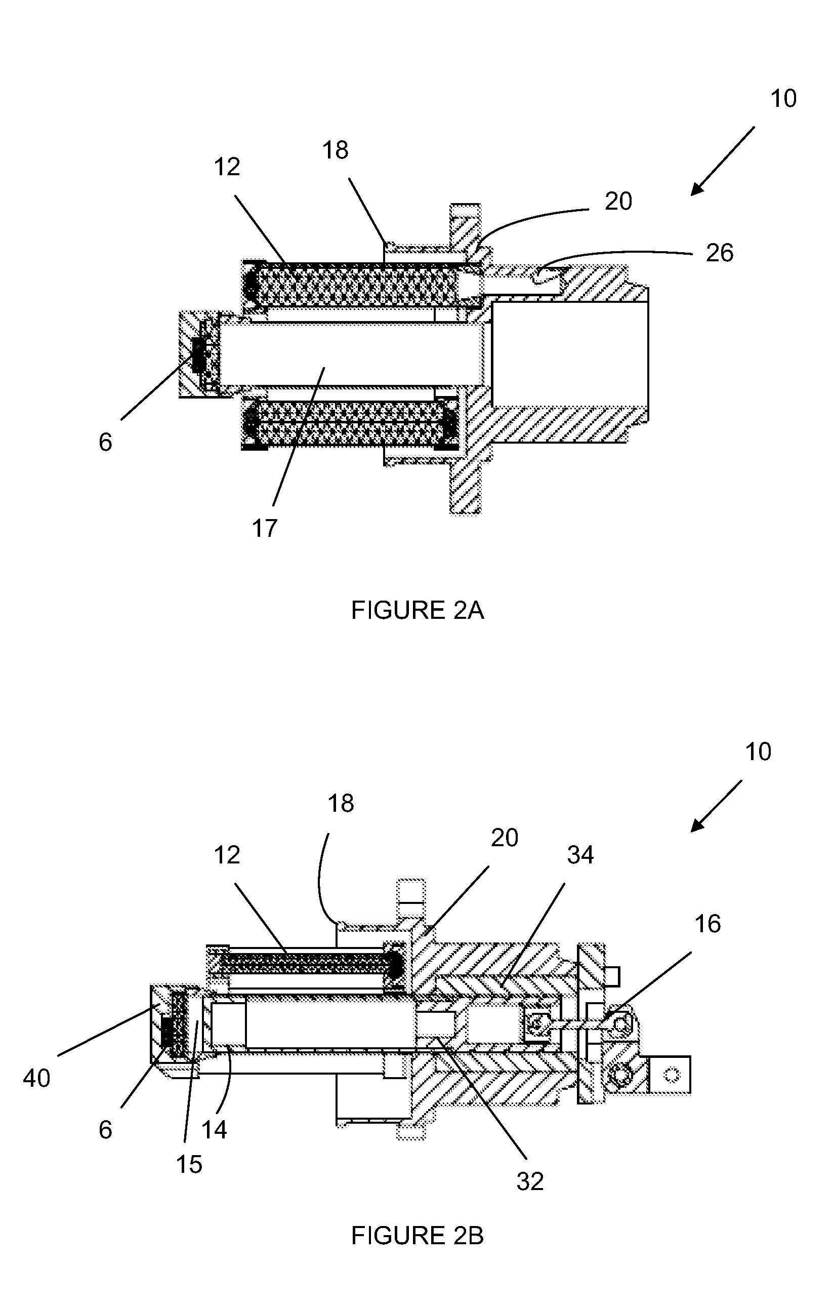
[0030]Embodiments of the invention are directed to an expander unit 10, which is usable in a Stirling engine or in a cryogenic cooler for an IR camera. As illustrated in FIGS. 2A, 2B and 3, regenerator matrix 12 is decoupled from displacer unit 14. Inventive regenerator matrix 12 is static, i.e., it does not move when displacer unit 14 undergoes reciprocating motion to displace the working gas in the Stirling thermodynamic cycle. Displacer unit 14 is connected (not shown) to displacer drive linkage 16, which is connected to the Stirling engine's driving motor. Reciprocal motions by displacer 14 expand the working gas in expansion space 15.

[0031]In this embodiment, regenerator matrix or regenerator 12 is placed outside the displacer 14 and inside a vacuumed Dewar enclosure (not shown), which includes Dewar adapter ring 18. In this embodiment, displacer unit 14 is a cylinder with a closed distal end that forms part of expansion space 15. Displacer unit 14 is slidingly received in a cy...


PUM


Abstract

The invention is directed to an improved cryogenic cooler with an expander where the regenerator matrix is decoupled from the displacer or piston, thereby allowing the design of each to be optimized substantially independently. The regenerator matrix is preferably positioned spaced apart from the displacer and can be designed to enhance thermal exchanges and flow rates of the working gas. In one embodiment, the regenerator matrix has a serpentine shape or U-shape disposed around the displacer and the cold finger. Preferably, the regenerator matrix is static. The thermal lengths of the cold finger and/or the displacer can be extended by minimizing their geometrical lengths. Additionally, the structural integrity or stiffness of the cold finger and/or displacer can be strengthened.

Description

FIELD OF THE INVENTION[0001]This invention generally relates to improved miniaturized Stirling engines having efficient regenerator, displacer and cold finger designs suitable for used in cryogenic coolers.BACKGROUND OF THE INVENTION[0002]Conventional Stirling Cycle Rotary Cooling Engines generally have a compressor and an expander connected to a crank mechanism driven by an electrical motor. The compressor, also known as a pressure wave generator. It is attached to the warm end of the expander and delivers acoustic power (compressor PV work) into the expander warm end inlet. Compressor PV work is the integration of the pressure-volume curve over one thermodynamic cycle or one complete revolution of the crank shaft. Compressor PV work has a unit of energy, and when derived over time, it is defined as acoustic power. The expander recovers this work at the cold end by causing the gas to expand and thus absorb heat from external power source such as an IR sensor. The gas expansion is a...

Claims


Application Information

Patent Timeline
Patent Type & Authority Applications(United States)
IPC IPC(8): F25B9/14
CPCF02G2250/31F25B2309/003F25B9/14
Inventor BIN-NUN, URISANCHEZ, JOSE PASCUALLEI, XIAOYANVIRK, USHA
Owner TELEDYNE FLIR LLC
Why Eureka
Try Eureka