
Solar power generation system with cone -shaped protrusions array

a solar power generation system and array technology, applied in solar heat systems, pv power plants, lighting and heating equipment, etc., can solve the problems of reducing the efficiency of solar cells, increasing the cost and time required for manufacturing solar panels, and overheating of pv cells parts, so as to achieve effective light energy collection and increase the effective area for absorbing

Inactive Publication Date: 2012-01-26
CHIENKUO TECHNOLOGY UNIVERSITY
View PDF5 Cites 9 Cited by
  • Summary
  • Abstract
  • Description
  • Claims
  • Application Information

AI Technical Summary

Benefits of technology

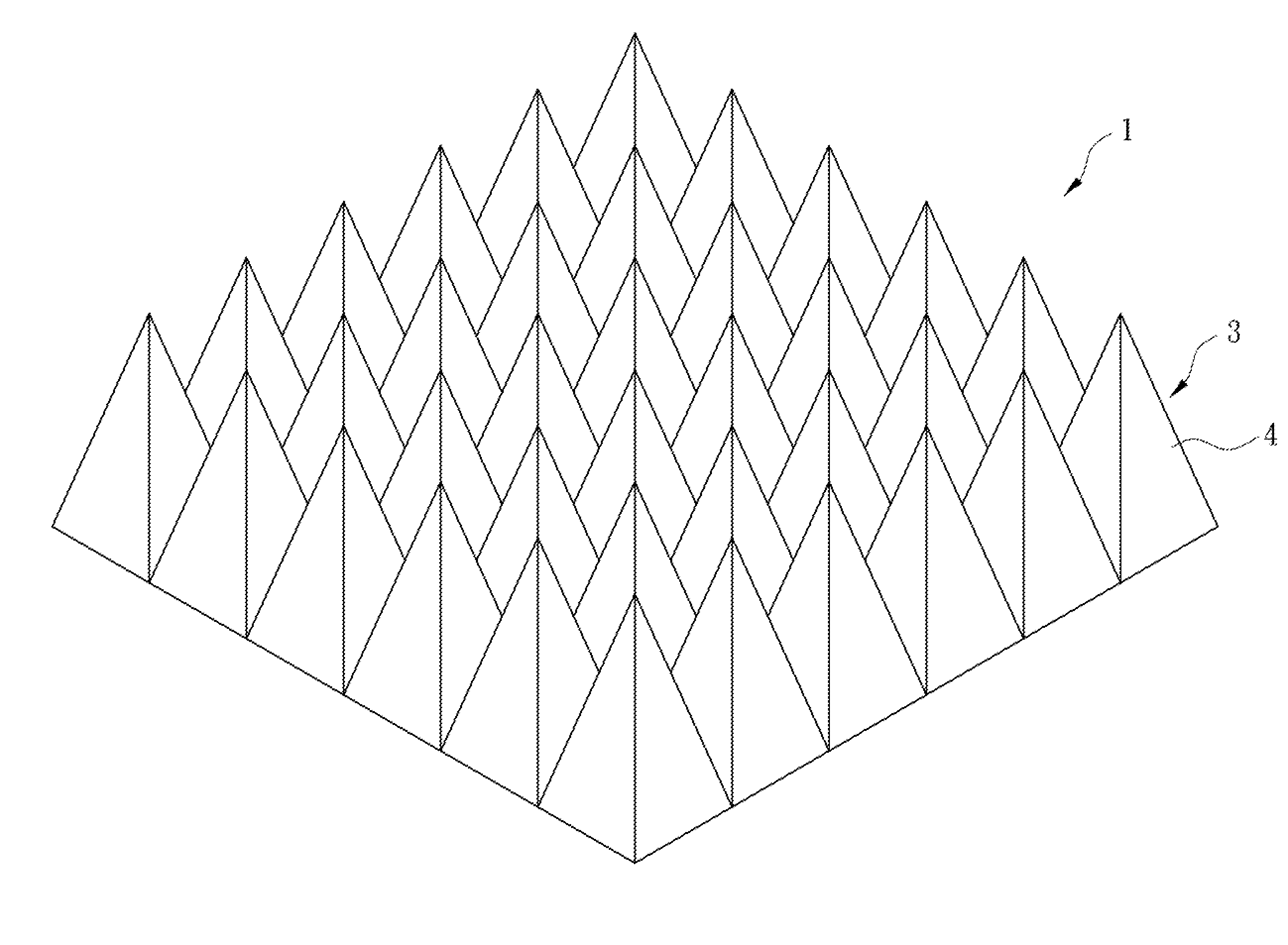
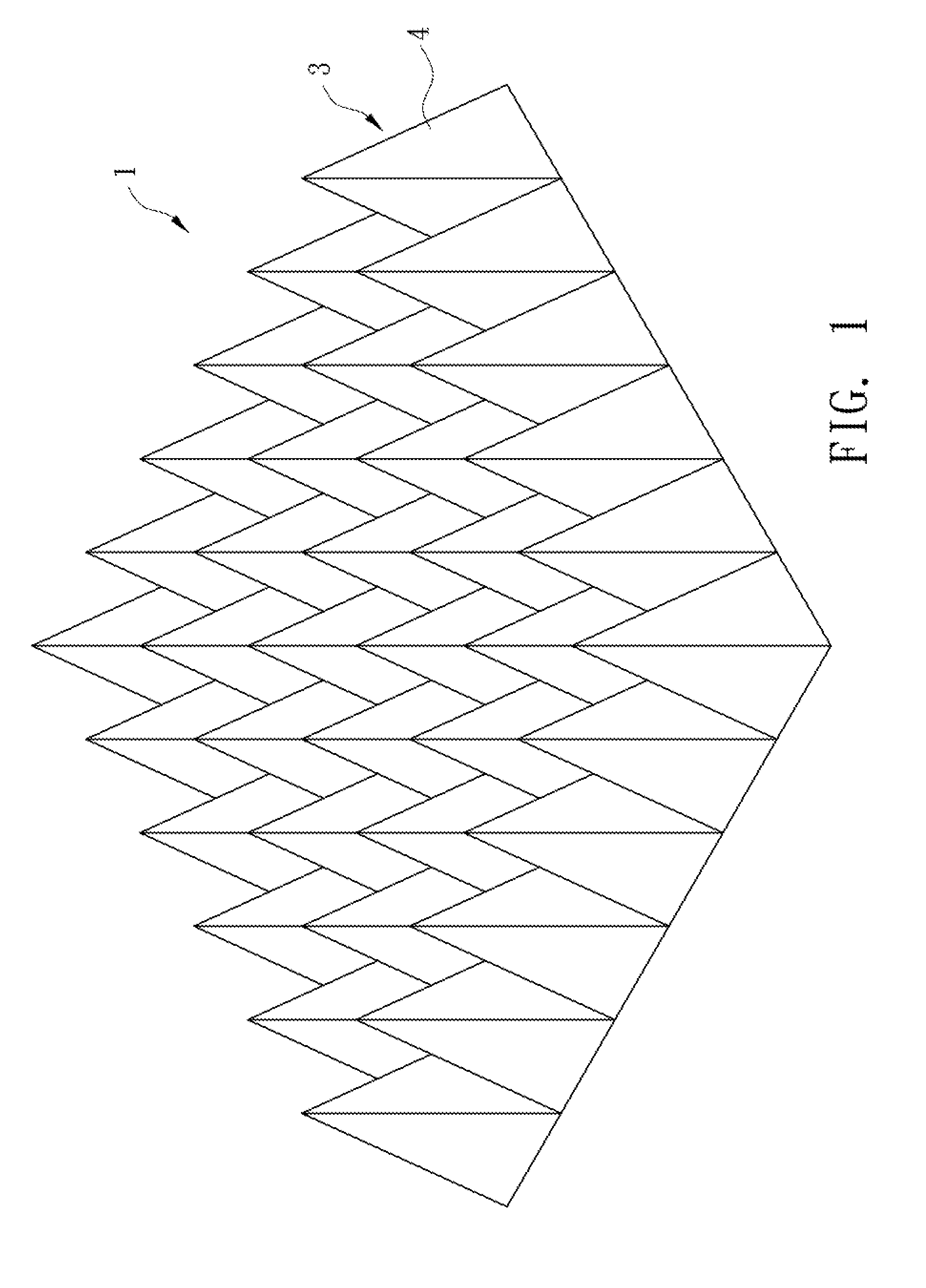
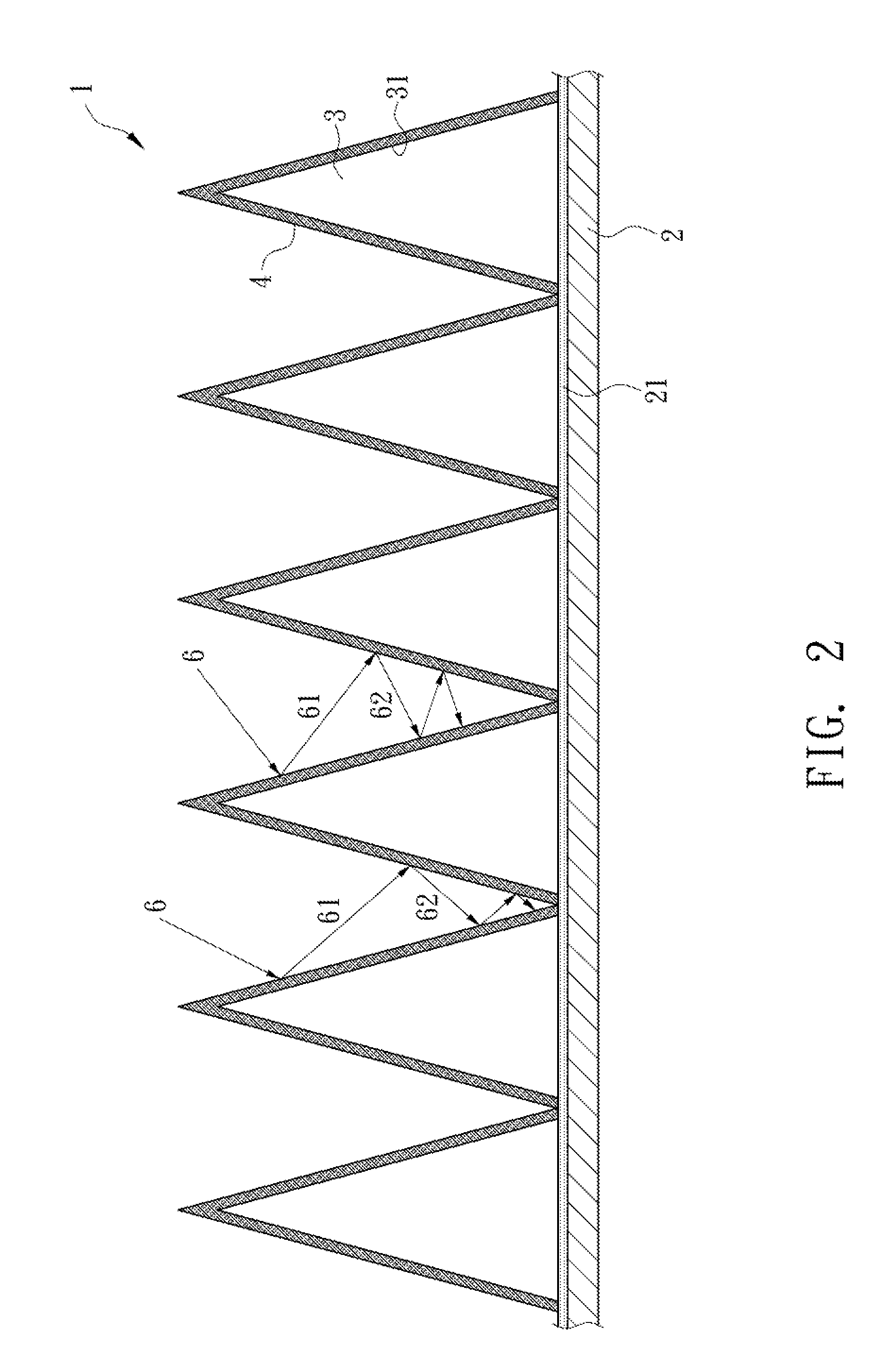
[0007]The main object of the present invention is to provide a solar power generation system which comprises multiple cones connected to a base in an array fashion and the adjacent surfaces between the cones with solar panels made by different materials. The solar panels on the boards of the cones can be any materials with different spectrum absorbing capabilities as mentioned above. When the incoming light reaches the boards of the cones, the light reflects, diffuses and is absorbed, just like entering a black hole and won't be released. Any angular board of the cones can absorb the reflected light of the same or different spectrums so as to increase the effective areas for absorbing the light. That means that the light energy can be effectively collected and the solar panels transfer the solar energy into electric energy, which is used to generate electric power.
[0008]Another object of the present invention is to provide a solar power generation system wherein air flows through the gaps between the cones to increase the convection heat transfer, so that the heat dispensing area increases; as the heat is dispensed quickly and the efficiency of the photovoltaic conversion will increase.
[0010]Yet another object of the present invention is to provide a solar power generation system wherein the manufacturing cost becomes low and there is no need to add anti-reflection layer as long as the angles of the cones are small and no incoming sunlight will escape from the array. And there will be no need to install the sun tracking system so as to reduce the time required and the cost for manufacturing.

Problems solved by technology

However, there is a flat surface located between the first conductive layer and the photoelectric conversion layer, before the incoming light is reflected into the photoelectric conversion layer, a part of the incoming light is reflected and scattered by the flat surface between the first conductive layer and the photoelectric conversion layer, and moves away from the photoelectric conversion layer, so that this part of the incoming light is not absorbed by the photoelectric conversion layer and the efficiency of the solar cells are reduced.
Therefore, some developers put an anti-reflection layer on the surface of the solar panel, but this will increase the cost and time required for manufacturing the solar panels.
Furthermore, the sunlight energy which is not transferred into energy in the solar cells escapes from the photovoltaic cells by way of reflection or it becomes thermal energy which is trapped in the solar cells to cause overheat to the parts of the PV cells.
The phenomenon of overheat reduces the conversion efficiency of the solar cells.
However, when the solar energy absorbed by the solar cells is doubled, the temperature increases dramatically and the heat cannot be quickly escaped from the package surface of the circuit board to the outside air.
Therefore, the efficiency of photoelectric conversion reduces.
Besides, the base board of the solar panel is a hard board and occupies certain space, it cannot be mounted to an irregular surface so that restriction of use is a problem and is one of the main concerns of the conventional solar power generation.
Nevertheless, the sun tracking system increases the cost due to maintenance and consums of electric power.

Method used


Image

  • Solar power generation system with cone -shaped protrusions array
  • Solar power generation system with cone -shaped protrusions array
  • Solar power generation system with cone -shaped protrusions array

Examples


second embodiment

[0027]FIG. 3 shows the present invention, wherein the cones 3 is connected to each other by high sets 32 to form the solar power generation system 1. Each hinge set 32 comprises a hinge member 321 and a pin 323. The hinge member 321 includes a hole 322. Any two adjacent cones 3 respectively contain a hinge member 321 and a pin 323 which extends through the hole 322 and is pivotably connected to the hinge member 321. By this way, the bottom of the solar power generation system 1 is flexible and can be applied on different irregular surfaces.

third embodiment

[0028]FIG. 4 shows the present invention, wherein the base 2 includes multiple cones 3 in array form and each cone 3 contains multiple boards 33 or each cone 3 is a single cone-shaped solar power generation system with multiple surfaces. The boards 33 replaces the base of the solar panel and the solar panels 41 is connected to the boards 33 of the cones 3 by way of coating. The solar panels 41 each comprise a first conductive layer, a photoelectric conversion layer and a second conductive layer. The solar panel in this embodiment can be made more quickly and efficient.

fourth embodiment

[0029]The fourth embodiment is not disclosed in the drawings and the conductive layers of the solar panels 4 of the cones 3 output pre-set currents and voltages by way of parallel circuits or serial circuits.

[0030]While we have shown and described the embodiment of the present invention, it should be clear to those the state-of-the-art creatation that further embodiments may be made without distracting the scope of the present invention.


PUM


Abstract

A solar power generation system includes multiple cones connected to a base in an array fashion and each cone includes multiple solar panels connected to the boards thereof so that the incoming light is fully absorbed and most of the spectrum of light energy will convert into electric energy by the different solar panels on any board of the cones. The cone-shaped array solar power generation system includes larger absorbing area to absorb light from different angles and the efficiency of photoelectric conversion of the solar power generation system increases. The cone-shaped array increases mechanical strength of the solar panels, and is easily to be cleaned up and also lowers the temperature of the solar panels.

Description

FIELD OF THE INVENTION[0001]The present invention relates to a solar power generation system, and more particularly, to a photovoltaic system which utilizes black body radiation effect, and does not need to coat an anti-reflection layer on the solar panel and the solar tracking system. The solar power generation system absorbs full spectrum of the full incoming sunlight and transfers the sunlight into electric energy via different solar panels on the surfaces of the cone-shaped protrusions. The system has reinforced mechanical strength and better heat dispensing feature. The protrusions are able to be installed on an object with irregular surface.BACKGROUND OF THE INVENTION[0002]Due to increasing demand for new energy to meet requirements of the modern living way, the energy from the earth is gradually exhausted and a new replacement energy source is needed. The solar energy is one of the replacement energy which is a battery made of semi-conductive material and the solar battery tr...

Claims


Application Information

Patent Timeline
Patent Type & Authority Applications(United States)
IPC IPC(8): H01L31/042
CPCF24J2/0015H01L31/0547Y02E10/52F24J2/06F24S23/00F24S20/25
Inventor SHYU, JIA-MINGLEE, SHEAH-YH
Owner CHIENKUO TECHNOLOGY UNIVERSITY
Learn More