
Steel for surface layer hardening treatment, surface layer-hardened steel part, and method of manufacturing the same

a technology of hardening treatment and steel, which is applied in the direction of heat treatment equipment, manufacturing tools, furnaces, etc., can solve the problems of difficult drastic improvement, limit of tempered hardness improvement at 300° c., and inability to increase the shape change of heat treatment, so as to prevent the deterioration of the dimensional accuracy of the part, the effect of high tooth surface fatigue strength

Inactive Publication Date: 2012-01-26
NIPPON STEEL CORP
View PDF0 Cites 26 Cited by
  • Summary
  • Abstract
  • Description
  • Claims
  • Application Information

AI Technical Summary

Benefits of technology

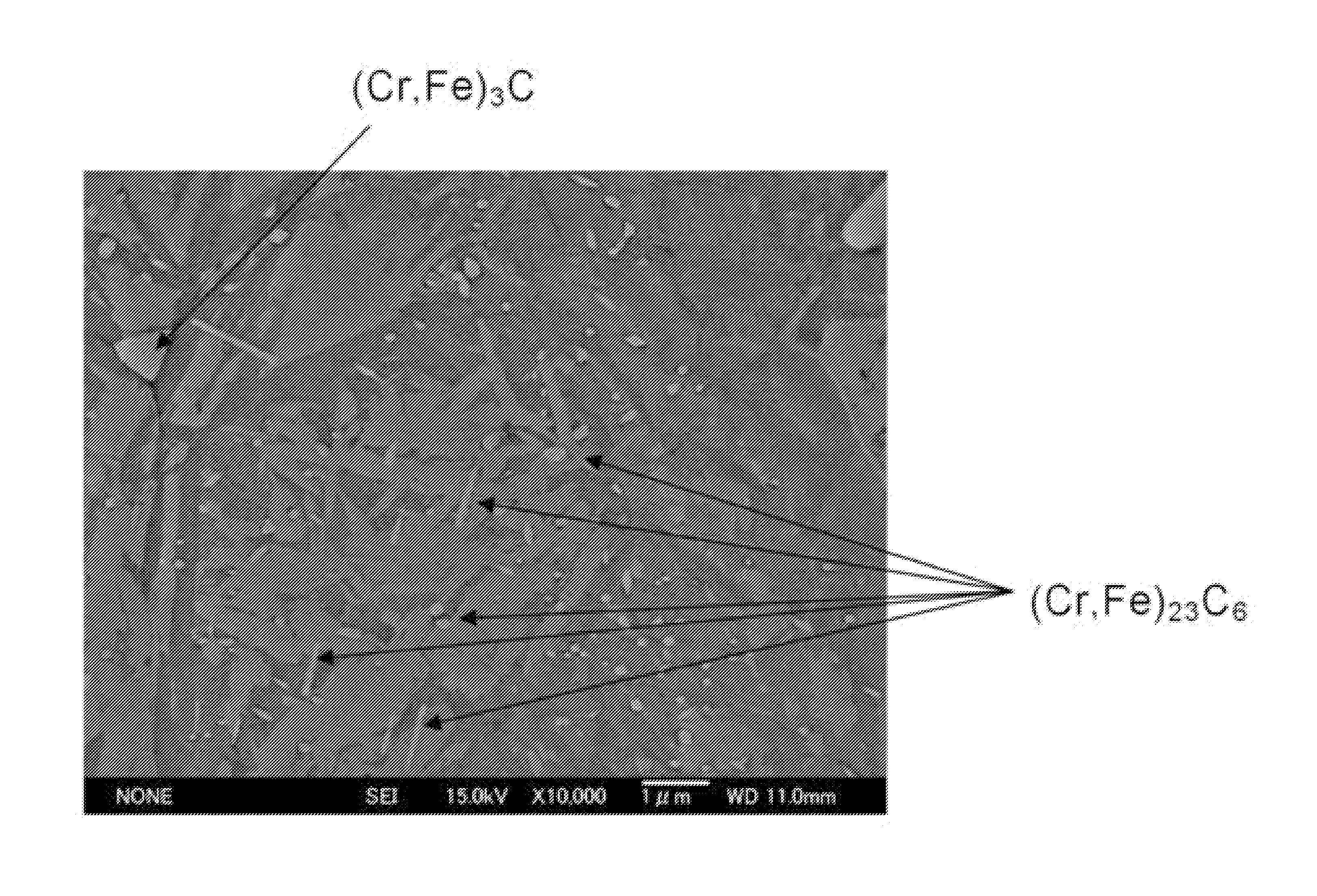
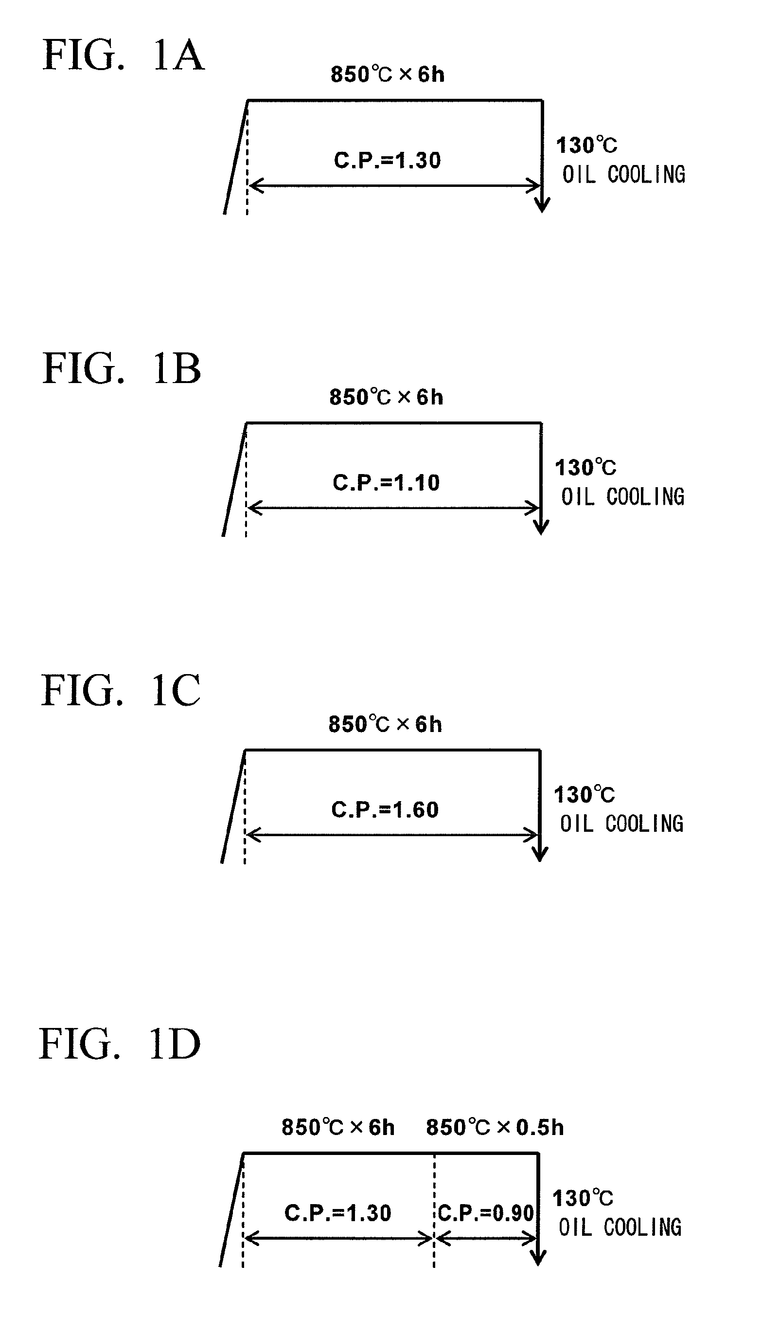
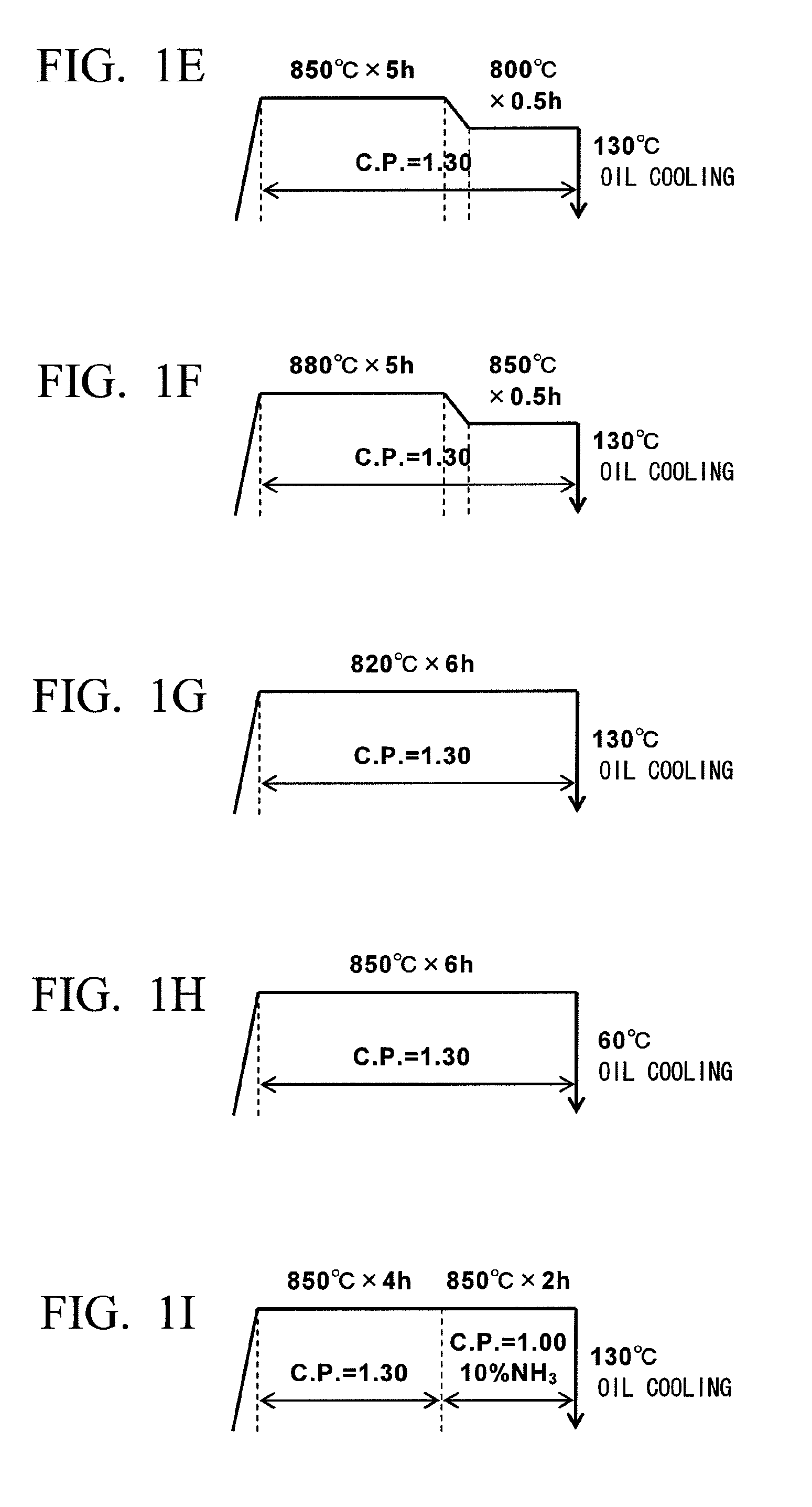
The present invention relates to a method of improving the surface fatigue strength of carburized steel parts, particularly for gear and bearing parts used in automobiles, construction machines, and wind turbines. The invention aims to drastically improve the tooth surface fatigue strength, which is an important characteristic for these parts. The invention proposes a high carbon carburizing treatment that intentionally precipitates cementite on the surface of the steel part, resulting in a microstructure with cementite dispersed in martensite. This technique is effective in improving the tempered hardness at 300°C, which is important for fatigue strength. However, when this treatment is applied to medium carbon alloy steel, coarse cementite precipitates and becomes a site where fatigue cracks initiate and a path of propagating the cracks, resulting in unstable bending fatigue strength. The invention proposes a method to improve the surface fatigue strength of carburized steel parts, particularly for gear and bearing parts, by controlling the carbon potential of the steel surface to a higher level and intentionally precipitating cementite on the surface of the steel part. This technique is effective in improving the tempered hardness at 300°C, which is important for fatigue strength.

Problems solved by technology

On the other hand, the tooth surface fatigue strength can hardly be improved even if the shot peening is performed, so the improvement of the tooth surface fatigue strength is anticipated.
However, even if the chemical composition of steel is optimized, the improvement of the tempered hardness at 300° C. has a limit and its drastic improvement is difficult.
On the other hand, carbide such as cementite or the like is much harder than martensite and not easily softened even when the temperature rises.
Therefore, the bending fatigue strength decreases and the tooth surface fatigue strength is unstable.
As a result, the problem such that the expected fatigue strength is not obtained occurs.
However, the secondary quenching not only raises the cost of the heat-treatment but worsens a performance of the part.
That is, the shape change of the part caused by the heat-treatment accumulates and increases inevitably by repetition of the heat-treatment.
Therefore, the dimensional accuracy of the part deteriorates.
For example, if the dimensional accuracy of parts of the gear and bearing deteriorates, the part causes an increase in noise and vibration, because the parts are put into a unit such as a transmission unit and the unit is driven.
However, since the cutting work is performed on the part including a surface layer portion which is extremely hardened by the high carbon carburizing, the cutting work is very difficult and inefficient, and the cost rises.
Accordingly, the carburizing treatment should be performed for many hours, and therefore, the productivity of the carburizing treatment decreases.
That is, in the current technique, although the secondary quenching should be performed to obtain the desired performance, the secondary quenching causes various problems, and as a result, a cost rises significantly.
However, since the diffusion treatment is performed at a temperature higher than the carburizing temperature, the carbide is coarsened.
Therefore, this method is unsuitable as a treatment replacing the secondary quenching.
This is substantially the same treatment as the secondary quenching, and this method cannot prevent the deterioration of the dimensional accuracy of the parts.

Method used


Image

  • Steel for surface layer hardening treatment, surface layer-hardened steel part, and method of manufacturing the same
  • Steel for surface layer hardening treatment, surface layer-hardened steel part, and method of manufacturing the same
  • Steel for surface layer hardening treatment, surface layer-hardened steel part, and method of manufacturing the same

Examples


example

[0134]Steels made molten by a converter having the component composition shown in Tables 1 and 2 were subjected to a continuous casting, a soaking diffusion treatment as necessary, and then a blooming rolling, thereby a rolling material of 162 mm square was manufactured. Thereafter, through hot rolling, the rolling material was shaped into a steel bar of 35 mm in diameter.

TABLE 1SteelComponents (% by mass)No.CSiMnPSCrNOCr + Si + MnRemarksA0.200.250.850.0150.0152.500.01350.00150.36Steel of theB0.200.250.800.0120.00013.000.00800.00244.05presentC0.200.230.800.0150.0152.250.01500.00153.28inventionD0.600.010.520.0050.1002.000.01400.00262.53E0.102.500.200.0100.0105.000.01200.00207.70F0.150.330.550.0080.0152.750.01300.00253.63G0.190.502.000.0100.0122.450.01250.00014.95H0.300.100.410.0120.0282.100.01350.00202.61I0.180.790.350.0060.0152.250.01000.00253.39J0.220.400.500.00010.0112.500.00200.00133.40K0.201.000.300.0100.0252.350.01450.00213.65L0.200.050.550.0080.0182.600.00600.00303.20M0.150.35...


PUM

PropertyMeasurementUnit
temperatureaaaaaaaaaa

Abstract

In the steel for a surface layer hardening which is treated with carburizing in a temperature range of 800° C. to 900° C., chemical composition thereof contains, by mass %, C: 0.10% to 0.60%, Si: 0.01% to 2.50%, Mn: 0.20% to 2.00%, S: 0.0001% to 0.10%, Cr: 2.00% to 5.00%, Al: 0.001% to 0.50%, N: 0.0020% to 0.020%, P: 0.001% to 0.050%, and O: 0.0001% to 0.0030%; the remaining portion thereof includes Fe and unavoidable impurities; and the total amount of Cr, Si, and Mn satisfies, by mass %, 2.0≦Cr+Si+Mn≦8.0.

Description

TECHNICAL FIELD[0001]The present invention relates to steel for a surface layer hardening treatment, a surface layer-hardened steel part, and a method of manufacturing the same.[0002]Priority is claimed on Japanese Patent Application No. 2010-064880, filed Mar. 19, 2010, the content of which is incorporated herein by reference.BACKGROUND ART[0003]Most power transmission parts (for example, a gear, a bearing, a CVT sheave, a shaft, and the like) used for automobiles, construction machines, farm machines, electricity generating-wind turbines, other industrial machines and the like are used after being subjected to a surface hardening treatment to improve, for example, fatigue characteristics and abrasion resistance of the parts. Among a plurality of known surface hardening treatments, a carburizing treatment is superior to other surface hardening treatments in terms of the surface hardness, depth of hardened layer, productivity, and the like, so the carburizing treatment is applied to...

Claims


Application Information

Patent Timeline
Patent Type & Authority Applications(United States)
IPC IPC(8): C23C8/32C22C38/60C22C38/08C22C38/18C22C38/22C22C38/16C23C8/22C22C38/06
CPCC21D9/32C21D9/40C21D2211/004C23C8/22C22C38/60C22C38/18C22C38/34C22C38/38C23C8/32F16G5/16C22C38/002C22C38/54
Inventor KUBOTA, MANABUOCHI, TATSURO
Owner NIPPON STEEL CORP
Learn More