Carbon dioxide reduction method, and carbon dioxide reduction catalyst and carbon dioxide reduction device used for the method

a carbon dioxide and catalyst technology, applied in the direction of electrolytic organic production, physical/chemical process catalysts, electrode coatings, etc., can solve the problems of large-scale equipment, high overvoltage, and reaction not proceeding smoothly, so as to reduce carbon dioxide and reduce carbon dioxide. , the effect of high durability

Inactive Publication Date: 2012-01-26
PANASONIC CORP
View PDF5 Cites 43 Cited by
  • Summary
  • Abstract
  • Description
  • Claims
  • Application Information

AI Technical Summary

Benefits of technology

[0010]Therefore, if a carbon dioxide reduction catalyst that is durable enough for practical use at a low overvoltage is achieved, carbon dioxide is allowed to be reduced to carbon monoxide, formic acid, methane, etc. and these substances are allowed to be provided at low cost and in an energy-saving manner. Such a carbon dioxide reduction technique is also very useful as a technique for reducing the amount of carbon dioxide. Furthermore, carbon dioxide reduction techniques are expected to be very useful as more environmentally-friendly resource recycling methods for the future if they are combined with photocatalytic technology and solar power generation.
[0011]Accordingly, it is an object of the present invention to provide a carbon dioxide reduction method and a carbon dioxide reduction device, in which carbon dioxide is reduced in a solution, and a catalytic material having high durability and capable of reducing carbon dioxide at an overvoltage equal to or lower than the overvoltages for the reduction in conventional methods and devices is used. It is a further object of the present invention to provide a carbon dioxide reduction catalyst capable of reducing carbon dioxide in a solution, having high durability, and capable of reducing carbon dioxide at an overvoltage equal to or lower than the overvoltages for the reduction by conventional carbon dioxide reduction catalysts.
[0012]The carbon dioxide reduction method of the present invention is a method including steps of: bringing an electrode containing a carbide of at least one element selected from Group V elements (vanadium, niobium, and tantalum) into contact with an electrolytic solution; and introducing carbon dioxide into the electrolytic solution to reduce the introduced carbon dioxide by the electrode.
[0015]The carbon dioxide reduction method and the carbon dioxide reduction device of the present invention are a method and a device for reducing carbon dioxide in a solution, and further use, for an electrode (first electrode) for reducing carbon dioxide, a catalytic material having high durability and capable of reducing carbon dioxide at an overvoltage equal to or lower than the overvoltages for the reduction in conventional methods and devices. Therefore, the method and the device of the present invention achieve reduction of carbon dioxide to carbon monoxide, formic acid, methane, etc. and provide these substances with less energy and at lower cost. Furthermore, the catalyst of the present invention achieves reduction of carbon dioxide in a solution, has high durability, and achieves reduction of carbon dioxide at an overvoltage equal to or lower than the overvoltages for the reduction by conventional carbon dioxide reduction catalysts.

Problems solved by technology

However, the above-mentioned conventional materials for electrode catalysts capable of reducing carbon dioxide in a solution have a problem in that they still require a high overvoltage, and that the reaction does not proceed smoothly.
Such conventional materials also have a durability problem in that they deteriorate with time during the long-time catalytic reaction.
Meanwhile, the above-mentioned method for reducing carbon dioxide by reacting carbon dioxide not in a solution but with hydrogen, etc. under high temperature and high pressure conditions requires high temperature and high pressure conditions for the reaction, which requires large-scale equipment.
Furthermore, in this carbon dioxide reduction method, not only a reducing gas such as hydrogen must be prepared additionally but also a great deal of energy must be input.

Method used


Image

  • Carbon dioxide reduction method, and carbon dioxide reduction catalyst and carbon dioxide reduction device used for the method
  • Carbon dioxide reduction method, and carbon dioxide reduction catalyst and carbon dioxide reduction device used for the method
  • Carbon dioxide reduction method, and carbon dioxide reduction catalyst and carbon dioxide reduction device used for the method

Examples


example 1

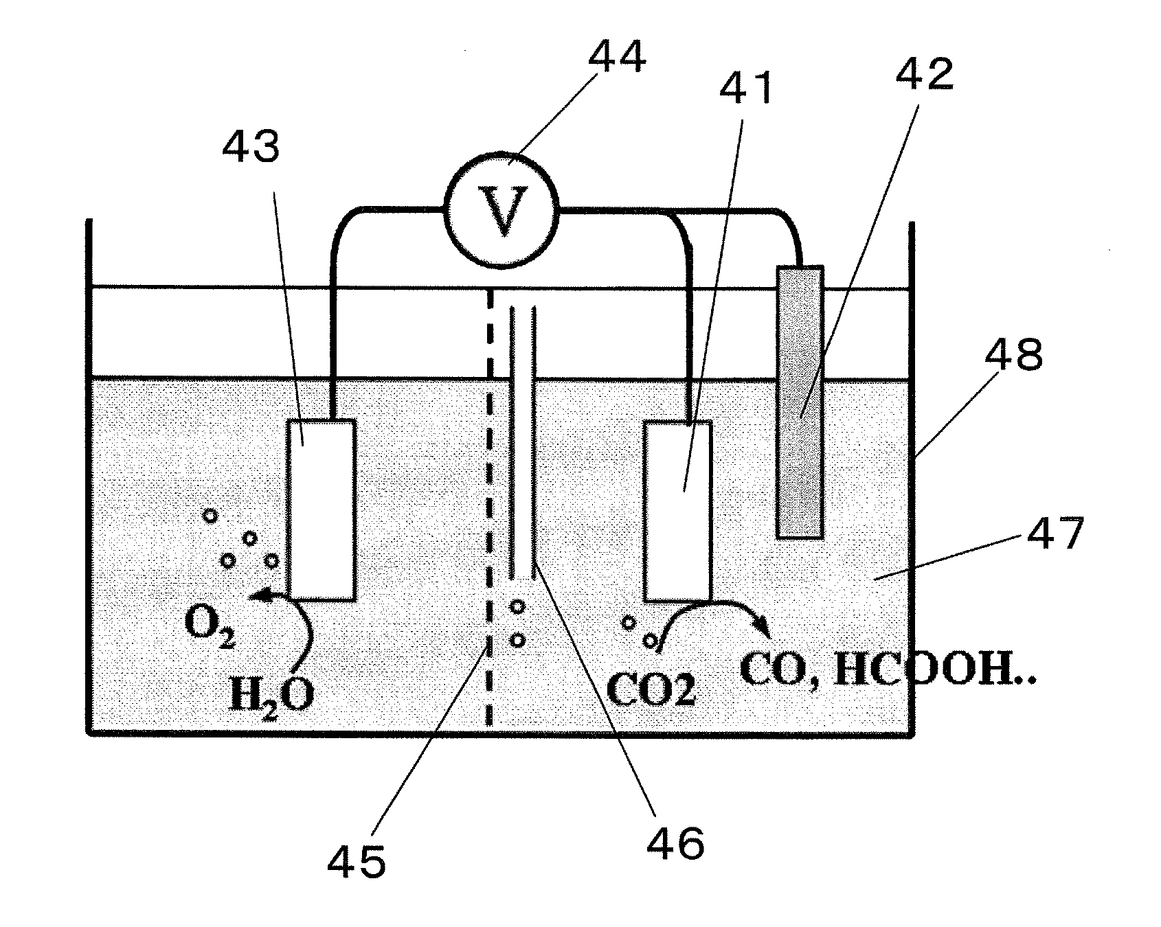
[0043]First, as an electrode substrate, a 1 cm square conductive silicon substrate was prepared. A chamber was pumped down to a vacuum of 1.0×10⁻⁴ Pa, and then argon gas was introduced into the chamber. A thin film of tantalum carbide was deposited at a thickness of about 3000 Å on the electrode substrate by sputtering at a power of 100 W in an argon gas atmosphere of 1.0×10⁻¹ Pa. The crystalline structure of tantalum carbide was evaluated by X-ray diffraction. FIG. 3 shows the X-ray diffraction pattern of tantalum carbide. As shown with arrows in the diffraction pattern of FIG. 3, peaks corresponding to the crystalline structure of tantalum carbide having a sodium chloride structure were observed.

[0044]This result of the X-ray diffraction confirmed that a crystalline thin film of tantalum carbide was deposited on the silicon substrate (electrode substrate), although tantalum carbide thus deposited was in a polycrystalline state having different plane indices.

[0045]FIG. 4 shows a sc...


PUM

PropertyMeasurementUnit
pressureaaaaaaaaaa
overvoltageaaaaaaaaaa
durabilityaaaaaaaaaa

Abstract

The carbon dioxide reduction method of the present invention is a method including steps of: bringing an electrode (working electrode) containing a carbide of at least one element selected from Group V elements (vanadium, niobium, and tantalum) into contact with an electrolytic solution; and introducing carbon dioxide into the electrolytic solution to reduce the introduced carbon dioxide by the electrode. The material contained in the electrode, that is, the material containing a carbide of at least one element selected from Group V elements (vanadium, niobium, and tantalum) is the carbon dioxide reduction catalyst of the present invention.

Description

BACKGROUND OF THE INVENTION[0001]1. Field of the Invention[0002]The present invention relates to a carbon dioxide reduction method, and a carbon dioxide reduction catalyst and a carbon dioxide reduction device used for the method.[0003]2. Description of Related Art[0004]Conventionally, the development of electrode catalysts capable of electrolytically reducing carbon dioxide in a solution has focused on solid metals such as copper and silver and metal complexes such as cobalt complexes and iron complexes.[0005]Carbon dioxide is generally a very stable molecule. Conventionally, electrical reduction of carbon dioxide requires a very high overvoltage. There are not many catalysts capable of reducing the overvoltage. Various materials have been studied as catalysts, but significant results have not been obtained. Furthermore, metals (including alloys) and molecular materials have a durability problem in that they deteriorate with time when they are used as catalysts for a long time. The...

Claims


Application Information

Patent Timeline
Patent Type & Authority Applications(United States)
IPC IPC(8): C25B1/00C01B31/30C25B9/00C01B32/40C25B3/25
CPCB01J27/22C01B31/18C25B1/00C25B11/0447C25B3/04C01B32/40C25B3/25C25B11/075
Inventor YOTSUHASHI, SATOSHITANIGUCHI, REIKOZENITANI, YUJI
Owner PANASONIC CORP
Why Eureka
Try Eureka