Hybrid vertical energy storage system

a vertical energy storage and hybrid technology, applied in the field of energy storage and power systems, can solve the problems of increasing long-term operation and maintenance costs, affecting the life span of batteries and associated electronics, and not being able to use battery only storage technology, so as to eliminate the need for costly transmission and distribution infrastructure improvements and increase long-term operational maintenance costs.

Inactive Publication Date: 2012-01-26
HUGHEY CHARLES E
View PDF11 Cites 11 Cited by
  • Summary
  • Abstract
  • Description
  • Claims
  • Application Information

AI Technical Summary

Benefits of technology

[0058]This invention and strategy is also useful in that energy storage provides the best value when it can be installed near load centers. Distributed energy storage decreases, and, in volume use, eliminates the need for costly transmission and distribution infrastructure improvements and upgrades and / or additional fueled power plants. This is of tremendous value to the utility providers, as the long term operational maintenance costs increase with additional infrastructure.
[0059]The small footprint of the individual units allows a proportionately sized energy storage system to be located virtually anywhere, in new construction or as a retrofit system. Further, this invention allows capacity to be added at any time depending on the need and / or application.

Problems solved by technology

All of these systems have their own strengths, weaknesses and efficiencies.
The high current draws experienced in battery only based energy storage systems may be detrimental to the life span of the batteries and associated electronics.
This is not economically viable because charging and discharging batteries at high rates are detrimental to the batteries chemistry and shorten the batteries service life, which increases long term operation and maintenance costs.
This is not possible in a battery only storage technology as large current draws are a matter of function.
A battery management system must monitor all the batteries voltages and temperatures which is expensive and complicated.
However, there are many problem associated with pumped hydro, including geographical placement, environmental and facility installation cost, environmental impacts on existing ecosystems and the amount of time between conception and operation can and has taken decades.
The absence of these facilities requires expensive transmission lines to be installed to operate with the pumped hydro facility.
Also, the required economic capital is immense and includes a lengthy site selection process, environmental impact studies which can cost millions, construction costs which may total hundreds of millions of dollars and then there are the long term operational and maintenance costs.
The disadvantages of using pumped hydro energy storage are significant geographical placement hurdles as there must be a significant difference in elevation between the two bodies of water, high up front capital and environmental study costs, a decade or more of planning and construction, and finding geographical locations which are near electrical transmission and distribution facilities.
CAES is similar to pumped hydro in that the site itself is large and the site selection process is both lengthy and restrictive.
Underground caverns that are large enough and strong enough for meaningful energy storage are not easily found.
Lengthy and expensive environmental impact studies are also required of a CAES facility.
Also, geographically satisfactory locations for CAES systems are rarely near electrical transmission or distribution infrastructure, which requires expensive transmission lines to be installed to operate the CAES facility.
And while the compressed air may improve the efficiency of the fueled power plant, CAES does not provide a standalone and emission free energy storage system.
The disadvantages of using compressed air energy storage (CAES) are significant geographical and subterranean placement hurdles, high up front capital costs and finding geographical locations which are near electrical transmission and distribution facilities.
Further, current compressed air energy storage (CAES) technologies use the compressed air to assist a fueled power plant, which produces undesirable environmentally damaging emissions.
If any explosive gases were to enter the Heidenreich system and become compressed, and an ignition source such as an electrical failure or lightning ignited the mixture, the results could be catastrophic.
Further, Heidenreich does not disclose or teach using the components of the combined attribute energy storage system as the weighted component of a gravitationally aided energy storage device which converts, stores and produces energy.
Further, Halloran does not disclose the ability to add capacity at any time, nor does Halloran teach using the system outside of a buildings structure or at the top of a buildings structure.
While all of these existing forms of energy storage all have their own specific benefits, they also have economic, environmental and operations flaws which provides the need for improving the current state of the art in energy storage.

Method used


Image

  • Hybrid vertical energy storage system
  • Hybrid vertical energy storage system
  • Hybrid vertical energy storage system

Examples


Embodiment Construction

[0066]For the purposes of promoting an understanding of the principles of the invention, reference will now be made to the embodiments illustrated in the drawings, which will be described below. It will nevertheless be understood that no limitation of the scope of the invention is thereby intended. The invention includes any alterations and further modifications in the illustrated devices and described methods and further applications of the principles of the invention which would normally occur to one skilled in the art to which the invention relates.

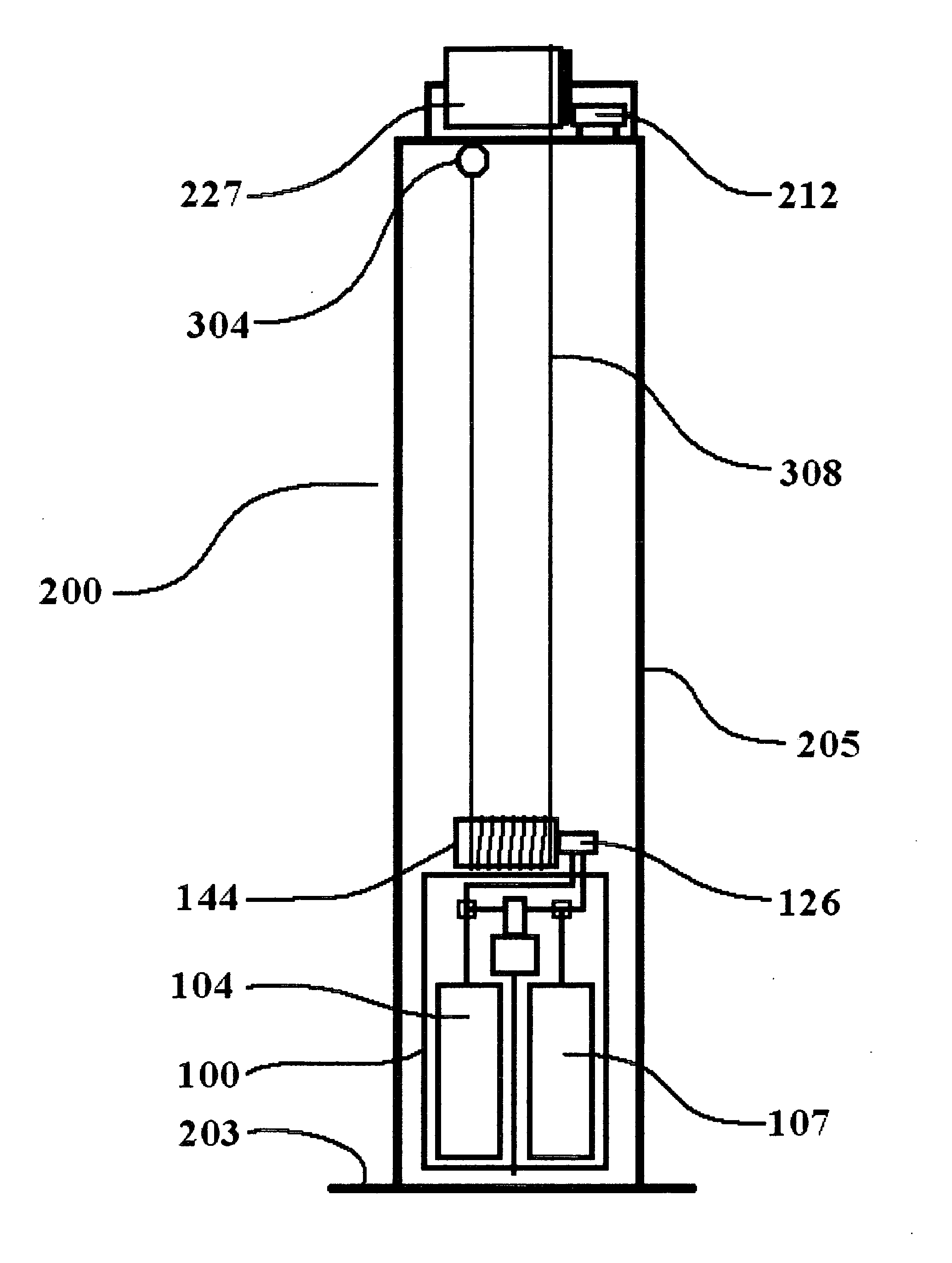
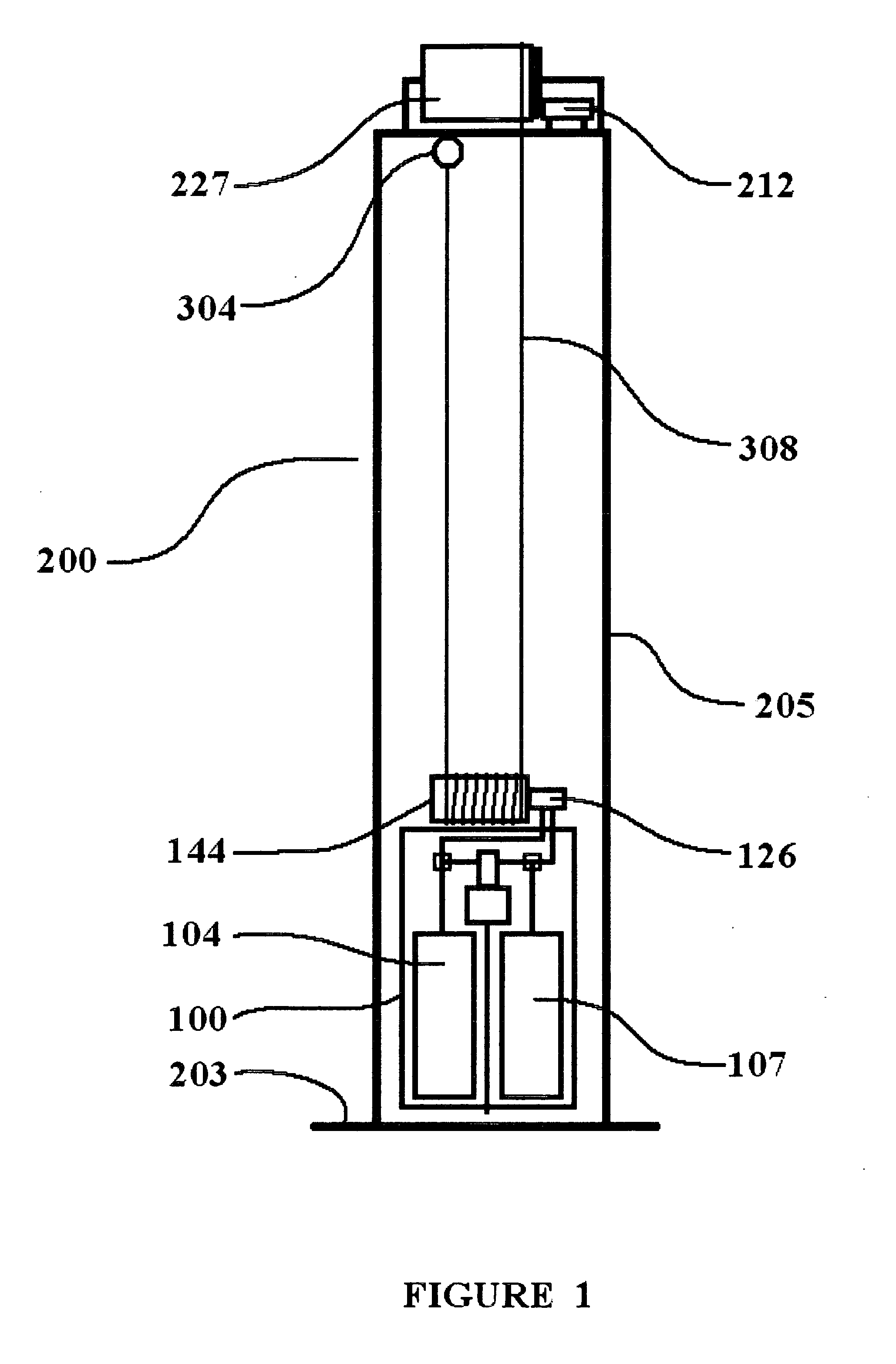
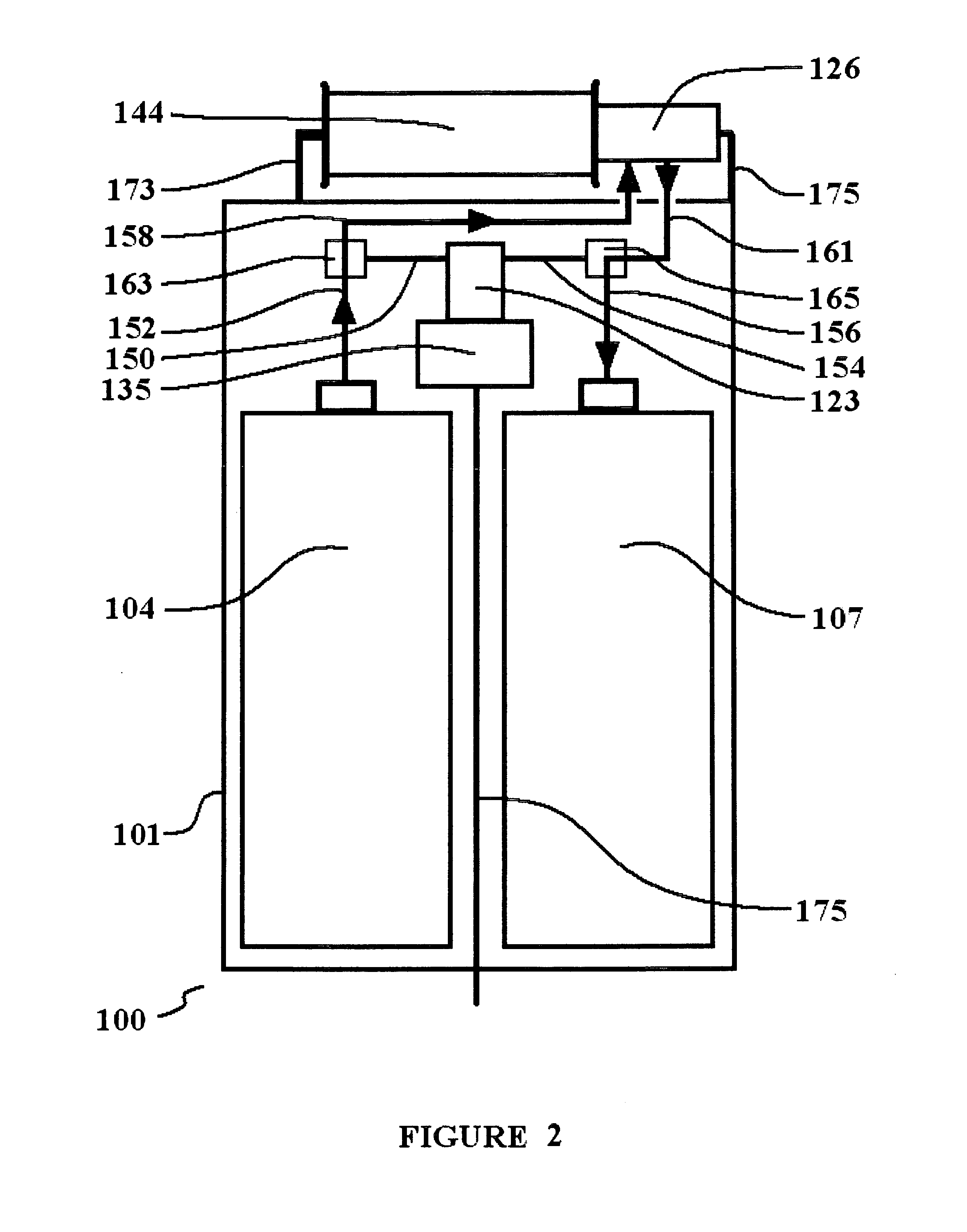
[0067]Referring now to FIG. 1, the energy storage system generally defined as 100 is composed of several components, and these components are housed in a component mounting structure referred to as 101. Component mounting structure 101 may be a metal box which in this embodiment may be approximately 4 feet tall and 12 inches square. Component mounting structure 101 may be made from and suitable material. Angle iron may compose its skel...


PUM


Abstract

A hybrid vertical energy storage system is invented wherein the components responsible for the conversion, storage and production of energy are used as the weighted component of a gravitationally aided energy storage device. The present invention allows gravity to operate mechanical devices which may help move a volume of fluid in order to compress a gas and store potential energy. The present invention utilizes the attributes of pumped hydro by using gravity assisted fluid transfer, and also combines Compressed Air Energy Storage (CAES) functionality by powering hydraulic pumps and motors to transfer fluid from one vessel to another vessel. This feature allows conventional, inexpensive, market proven components to make the capture, conversion, storage and production of energy more effective and affordable while eliminating the placement issues associated with such large scale pumped hydro and CAES systems while extending battery service life. Ideally, combining the positive attributes of some or all of the existing technologies into one energy storage system would provide a real and meaningful improvement, especially if the improvement reduced or eliminated economic, environmental and operational flaws associated with the individual technologies. This invention also provides a method of combining the output of individual, combined attribute energy storage systems to provide user definable and expandable electrical energy production. The vertical aspect of the invention allows operational attribute that separates and makes independent the capture and storage of energy being placed into the energy storage system and the hydro-pneumatic production of energy exiting the system.

Description

[0001]This patent application is a continuation-in-part and claims priority to the disclosures pending in U.S. Patent Application 61 / 400,298 to Applicant filed on Jul. 26, 2010, the complete disclosure of which is hereby expressly incorporated by reference.BACKGROUND OF THE INVENTION[0002]This invention relates to an energy storage and power system, and in particular an energy storage and power system that is of a hybrid design which combines existing, market proven components in a unique design which provides for the high efficiency capture, conversion, storage and production of energy.[0003]This invention includes a gravitational component to maximize the conversion, transfer and storage of energy, streamline the design and increase overall system efficiency. The system is scalable in size and capacity.[0004]This invention has many applications and there are many architectures upon which the same basic purpose, function and operation can be achieved by altering the general system ...

Claims


Application Information

Patent Timeline
Patent Type & Authority Applications(United States)
IPC IPC(8): H02K7/18
CPCH02K7/1823
Inventor HUGHLEY, CHARLES E.
Owner HUGHEY CHARLES E
Why Eureka
Try Eureka