
Radar tomography apparatus and method

a tomography and camera technology, applied in the field of tomography cameras, can solve the problems of reducing the quality of obtained data, increasing the complexity of problems, increasing the number of transceivers used, etc., and achieving the effects of reducing the computational demand for evaluating and processing acquired data, accelerating data acquisition, and reducing the computational demand

Active Publication Date: 2012-01-26
SONY CORP
View PDF3 Cites 27 Cited by
  • Summary
  • Abstract
  • Description
  • Claims
  • Application Information

AI Technical Summary

Benefits of technology

[0007]It is an object of the present invention to provide a radar tomography device and method, by which both the process of radar tomography, i.e. the acquisition of data, can be accelerated and the computational demand for evaluating and processing the acquired data can be reduced. It is a further object of the present invention to provide a corresponding computer program for implementing said method and a computer readable non-transitory medium.
[0022]Briefly summarized, the compressive sensing paradigm establishes that if a signal or image is sparse enough in some known domain, it can be reconstructed from a very few number of samples (much less than what Nyquist specifies), as far as the acquisition process can be randomized in some sense. Hence, the present invention proposes to reduce the data acquisition time of a radar tomography apparatus by applying compressive sensing. Consequently, the compressive sensing technology is applied in the processing of the acquired sparse pattern of the electromagnetic field values to construct the material properties at a high number or even all the mesh elements leading to the desired advantages over the known radar tomography devices and methods, in particular leading to the desired reduction in processing time. Further, an increase in the resolution of an image that can be reconstructed from the obtained material properties can be obtained if desired.
[0025]The solution proposed according to the present invention is to reduce the data acquisition and processing time by determining fewer electromagnetic field values in the forward solver than in a standard process, and then process the values by applying compressive sensing using the sparse representation of the material properties of the object under study (like, for example, total variation).
[0026]The application of compressed sensing proposed according to the present invention varies from current state of the art methods where it is applied to “Computed Tomography (CT)”. There, a linear relation between the measurements and the image is usually assumed as, for instance, disclosed in H. Yu and G. Wang, “Compressed Sensing based interior tomography”, Physics in Medicine and Biology, October 2009. Assuming a linear relation between the electromagnetic fields and the image in radar tomography would be the straightforward solution for radar tomography; however, it has been found that the results will not be satisfactory unless prior information is known. Compressive sensing can be also employed to reduce the acquisition time in radar tomography as was done in “Photo-Acoustic Tomography (PAT)” as, for instance, described in Jean Provost and Frederic Lesage “The Application of Compressed Sensing for Photo-Acoustic Tomography”, IEEE Transactions on Medical Imaging, April 2009. This, however, will reduce the acquisition time but it only covers a limited view of the object.
[0027]An element of the present invention is to reconstruct the image by formulating the compressive sensing principle to suit the non-linear inverse scattering problem in radar tomography. The non-linear inverse scattering problem assumes a non-linear relation between the electromagnetic fields and the image (material properties). A model modeling such a relation is also used in breast cancer detection, as, for example, described in A. E. Bulyshev et al. “Three-dimensional vector microwave tomography: theory and computational experiments”, Inverse Problems, August 2004, because it results in high quality images. However, the use of such a model makes the computations time demanding since, when the material properties of the whole object needs to be determined, the number of mesh elements where the relation should be determined will be very large. Hence, according to the present invention the principle of compressive sensing is applied, e.g. for breast cancer detection, to reduce the computation time.

Problems solved by technology

Hence, the complexity of the problem increases dramatically with the increase in the mesh density and the number of transceivers used.
However, this solution also reduces the quality of the obtained result (e.g. of an image reconstructed from the determined material properties).
Another obvious solution is trying to limit the meshed area to the object or the region of interest, but this solution still has high complexity, especially in 3D, unless the dimension of the mesh elements (i.e. voxel size) is also large.

Method used


Image

  • Radar tomography apparatus and method
  • Radar tomography apparatus and method
  • Radar tomography apparatus and method

Examples


Embodiment Construction

[0036]Radar tomography is a well known technique to construct the material properties of objects. It can be applied in vast areas like biomedicine to study the properties of tissues and determine whether they are malignant or not. It has been applied for example to breast and lung cancer imaging. It has also been applied to detect clots in brains and to study the cardiac activities.

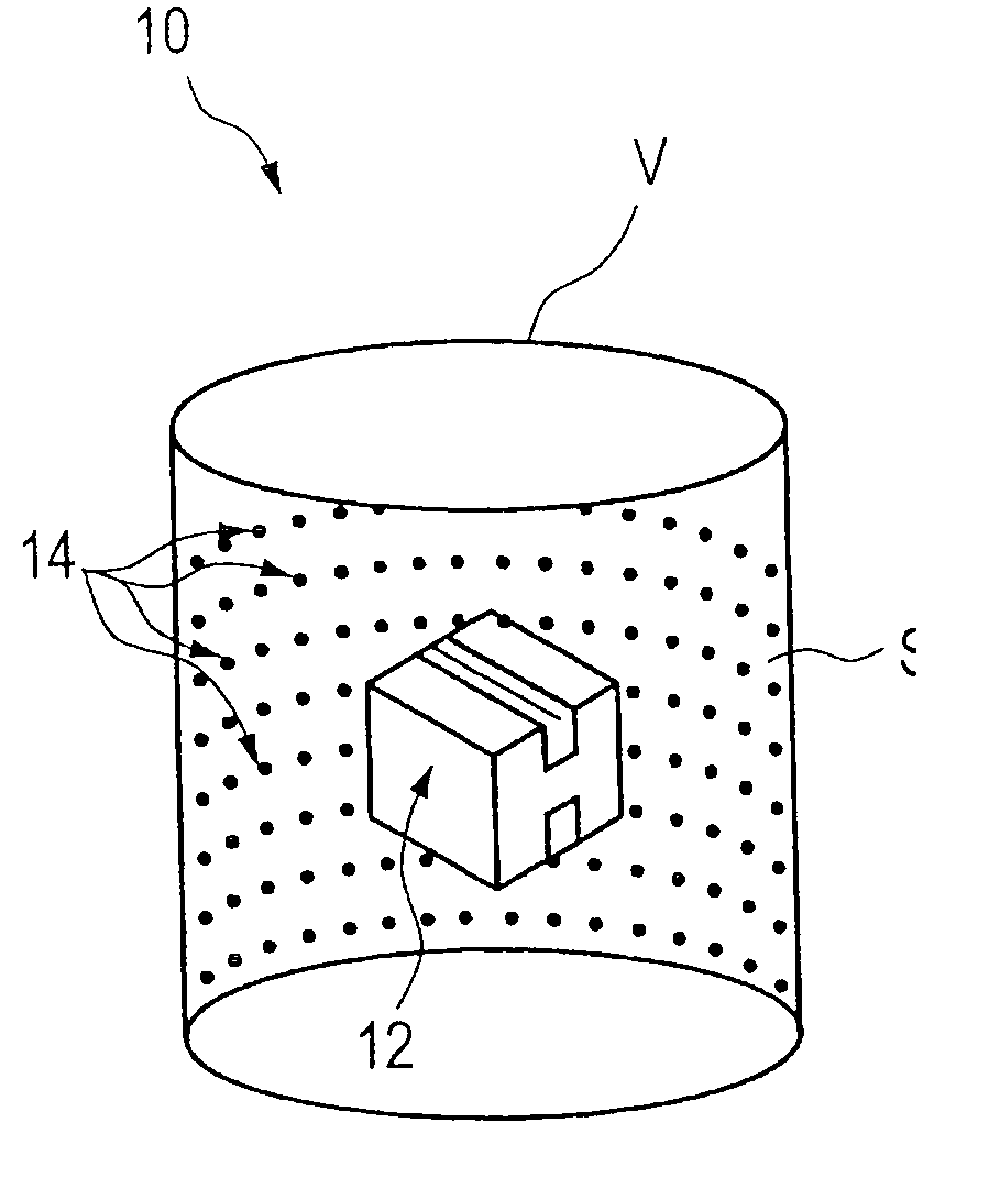
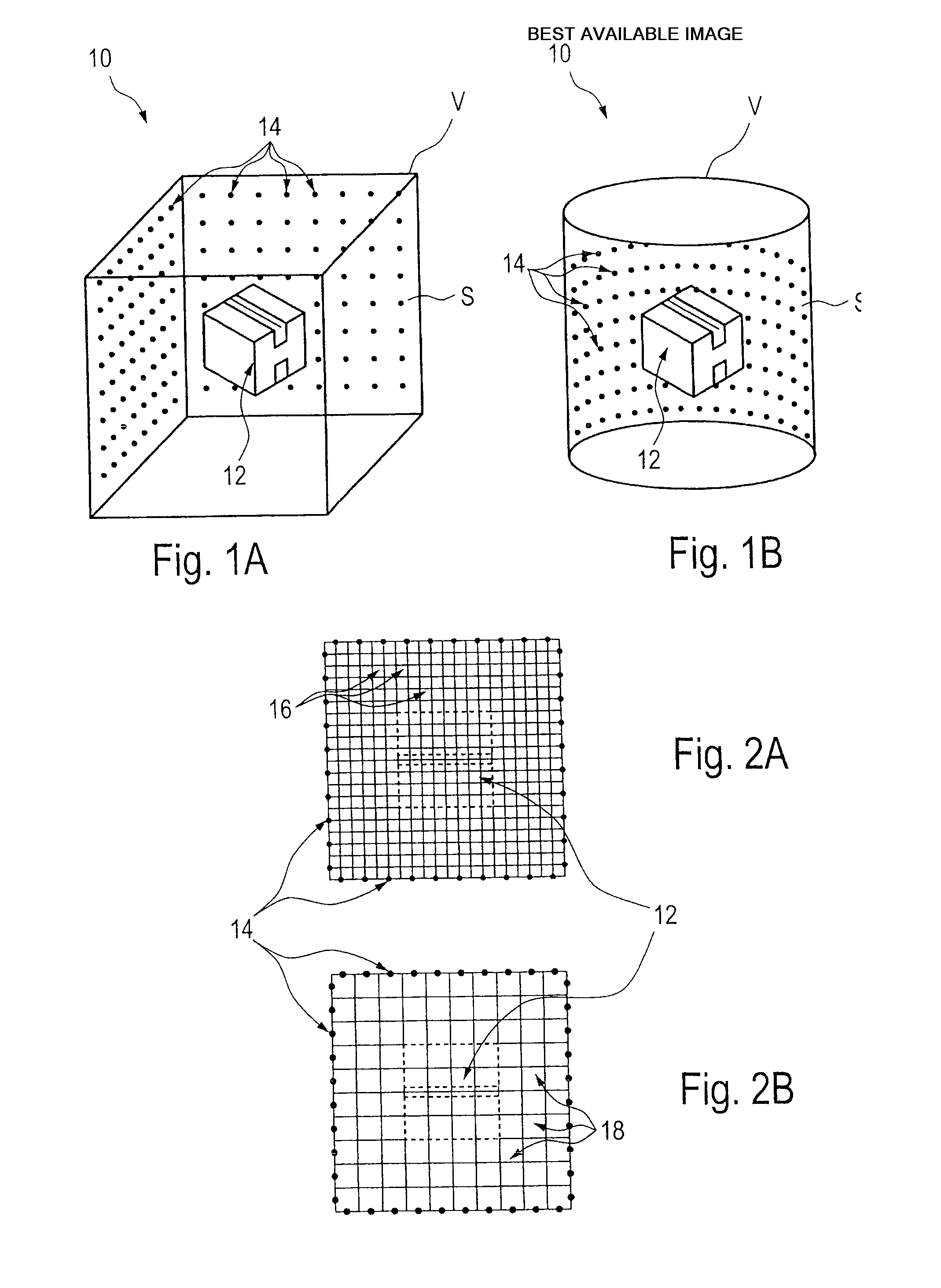
[0037]An embodiment showing the general layout of a radar tomography apparatus 10 is shown in FIG. 1. An object 12, e.g. a patient or a probe of tissue, is placed within a volume V that has the form of a cuboid (FIG. 1A) or a cylinder (FIG. 1B) for example (other formats are possible). On the surface S of this volume, an array of transceivers 14 is placed in a way to surround the object 12, wherein the transceivers can also be replaced by separate transmitters and receivers, which may be arranged at different positions and may be different in number.

[0038]The objective of radar tomography is to compute th...


PUM


Abstract

The present invention relates to a radar tomography apparatus and method for determining one or more material properties of an object at a first number of positions distributed within a region of interest of said object. To reduce the acquisition and processing time of data radar tomography apparatus is proposed comprising:one or more transmitters that transmit radiation, in particular microwave radiation, in the direction of the region of interest of the object,a plurality of receivers that receive radiation reflected from or transmitted through the region of interest of the object,a processor that processes the received radiation, said processor includinga forward solver that determines electromagnetic field values at a second number of positions distributed in the region of interest from the received radiation, wherein said second number is substantially lower than said first number, andan inverse solver that determines one or more material properties of the object at the first number of positions in the region of interest from the electromagnetic field values determined at said second number of positions in the region of interest by applying compressive sensing.

Description

CROSS-REFERENCE TO RELATED APPLICATIONS[0001]The present application claims priority of European patent application 10 169 816.5 filed on Jul. 16, 2010.FIELD OF THE INVENTION[0002]The present invention relates to a radar tomography apparatus and a corresponding method for determining one or more material properties of an object at a first number of positions distributed within a region of interest of said object. Further, the present invention relates to a computer program for implementing said method and a computer-readable non-transitory medium.BACKGROUND OF THE INVENTION[0003]The invention relates to radar tomography, according to which unknown material properties, in particular electromagnetic properties, of an object shall be measured. The concept of radar tomography is generally known, for instance from A. E. Bulyshev et al. “Three-dimensional vector microwave tomography: theory and computational experiments”, Inverse Problems, August 2004, Z. Q. Zhang et Q. H. Liu. “Three-Dim...

Claims


Application Information

Patent Timeline
Patent Type & Authority Applications(United States)
IPC IPC(8): G01S13/89
CPCA61B5/0507A61B5/7257A61B5/7232G01S13/87G01S13/89A61B5/726
Inventor SARKIS, MICHEL
Owner SONY CORP
Learn More