Method and configuration for the optical detection of an illuminated specimen

a technology of illumination and optical detection, applied in the field of microscopy, can solve the problems of reducing the signal-to-noise ratio, limiting the useful sample thickness of out-of-focus signals, and limited contrast and resolution enhancement effects, and achieves low light loss and high intensities.

Inactive Publication Date: 2012-01-26
CARL ZEISS MICROSCOPY GMBH
View PDF2 Cites 10 Cited by
  • Summary
  • Abstract
  • Description
  • Claims
  • Application Information

AI Technical Summary

Benefits of technology

[0006]According to the present invention, the advantages of structured illumination in the wide field (few optical components, high parallelization) are combined with the advantages of structured illumination along a line (partially confocal suppression of the background signal for maximum contrast, high intensities in the focus for nonlinear and linear specimen interactions). The proposed configuration makes it possible to rotate the scanning direction rapidly, variably, and precisely, and to adjust the relative phase angle of the imaged structured periodic structure by means of only two scanners. In addition, it enables a variably adjustable confocal detection while allowing only very low losses of light in the detection beam path. In this context, reference is also made to DE 10155002 A1, the disclosure of which is hereby incorporated by reference as if such disclosure were fully set forth herein.

Problems solved by technology

The disadvantage is that the signal from out-of-focus regions of the specimen is detected as well, which, because of the limited dynamic region of the detector, leads to a reduced signal-to-noise ratio.
The strength of the out-of-focus signal limits the useful sample thickness.
As a result, the effects of contrast and resolution enhancement are limited to this direction.

Method used


Image

  • Method and configuration for the optical detection of an illuminated specimen
  • Method and configuration for the optical detection of an illuminated specimen
  • Method and configuration for the optical detection of an illuminated specimen

Examples


Embodiment Construction

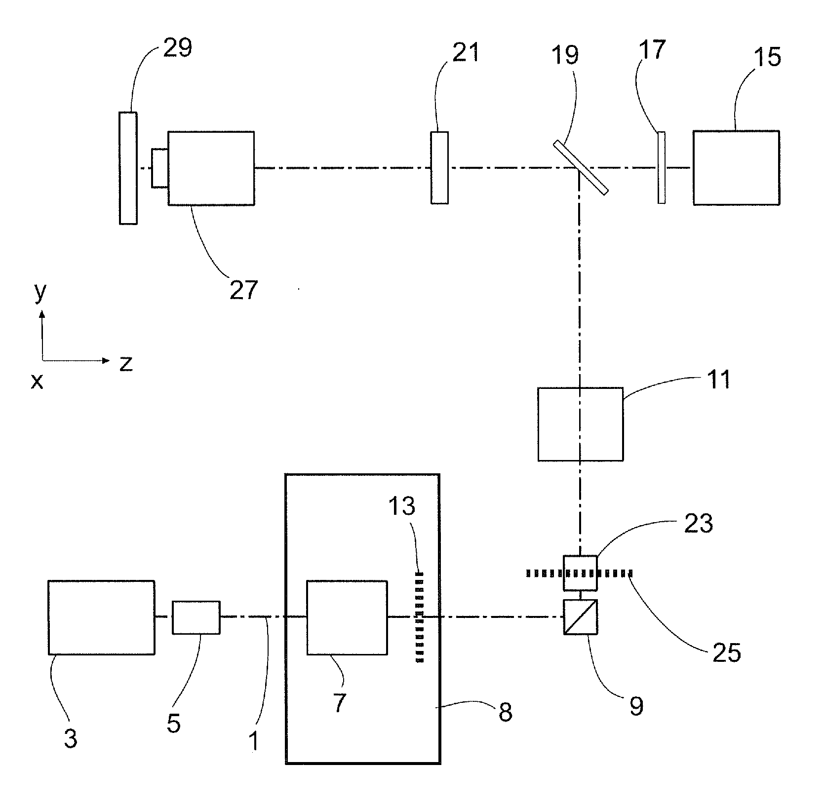
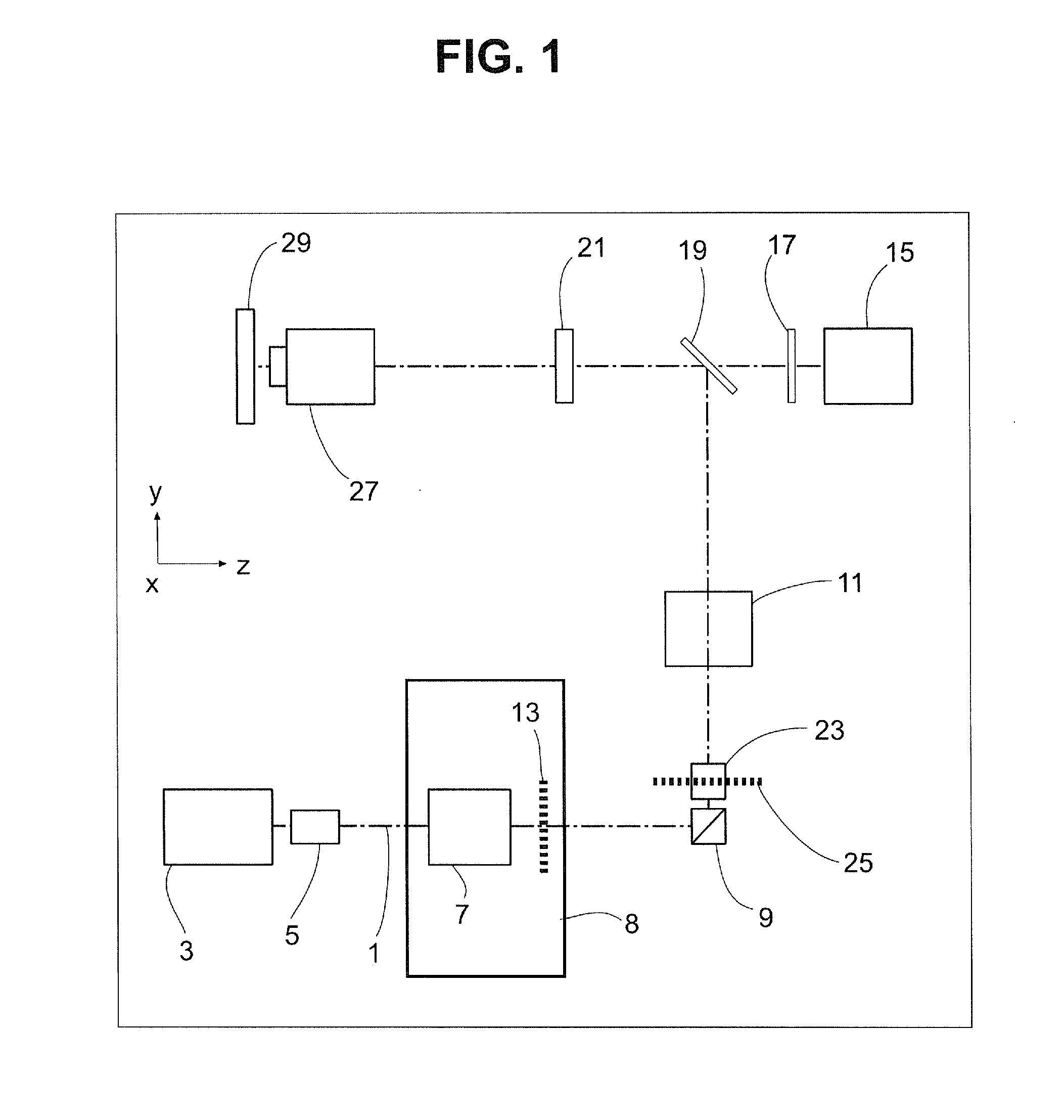
[0018]FIG. 1 shows the schematic assembly of the microscope according to the present invention. (1) is the optical axis, (3) is the light source, (5) is a switchable attenuator / AOM, (8) is a beam-shaping unit with a line-shaping optics system (7), for example, a cylindrical lens, (9) is scanner with an axis of rotation perpendicular to the drawing plane, (23) is a scanner with an axis of rotation (25) substantially parallel to the drawing plane, (11) is a scanning optics system, (13) is a mask with a periodic structure in the intermediate image plane conjugate to the specimen, (15) is a spatially resolved area sensor, e.g., a CCD receiver matrix, (17) is an emission filter, (19) is a main color divider, (21) is a barrel lens, (27) is a microscope lens, and (29) is the specimen. The elements (7) and (13) are combined to form a single mechanical group, the beam-shaping unit (8), which is preferably disposed so as to be able to rotate about the optical axis (1).

[0019]Next, shifting the...


PUM


Abstract

A method and a configuration for the depth-resolved optical detection of a specimen, in which a specimen or a part of the specimen is scanned by means of preferably linear illumination. The illumination of the specimen is periodically structured in the focus in at least one spatial direction. Light coming from the specimen is detected and images of the specimen are generated. At least one optical sectional image and/or one image with enhanced resolution is calculated through the specimen. Images are repeatedly acquired and sectional images are repeatedly blended while changing the orientation of the linear illumination relative to the specimen and/or spatial intervals between lines exposed to detection light from the illuminated specimen region are generated for the line-by-line non-descanned detection on an area detector or a camera and/or, during a scan, light is further deflected upstream of the detector through the line in the direction of the scan of the specimen.

Description

CROSS REFERENCE[0001]This application claims the benefit of U.S. provisional patent application 60 / 990,016 filed on Nov. 26, 2007, the contents of which are hereby incorporated by reference herein.FIELD OF THE INVENTION[0002]The present invention relates generally to the field of microscopy, and more particularly to microscopy in which structured illumination is used for depth discrimination in the wide field and for enhancing resolution and contrast.BACKGROUND OF THE INVENTION[0003]In microscopy, structured illumination is used for depth discrimination in the wide field [1]1 and for enhancing the resolution and the contrast [2]. Generally, a grating or another periodic structure is projected into the specimen [3] or an interference pattern is generated in the specimen by means of interference of coherent component beams [4]. By shifting the illumination structure, images are generated that differ from one another with different phase angles of the period structure. Subsequently, th...

Claims


Application Information

Patent Timeline
Patent Type & Authority Applications(United States)
IPC IPC(8): H04N7/18
CPCG01B9/04G01B11/24G02B21/0032G02B26/127G02B21/0036G02B27/0031
Inventor KEMPE, MICHAELWOLLESCHENSKY, RALFSCHWERTNER, MICHAEL
Owner CARL ZEISS MICROSCOPY GMBH
Why Eureka
Try Eureka