
Porous metal substrate structure for a solid oxide fuel cell

Active Publication Date: 2012-01-26
INST NUCLEAR ENERGY RES ROCAEC
View PDF7 Cites 10 Cited by
  • Summary
  • Abstract
  • Description
  • Claims
  • Application Information

AI Technical Summary

Benefits of technology

[0009]It is one object of the present invention to provide a porous metal supporting substrate structure with improved gas permeability by acid etching method.
[0010]It is another object of the present invention to provide a porous metal supporting substrate structure with improved anode redox stability for supporting a SOFC.
[0011]It is another object of the present invention to provide a porous metal supporting substrate with a surface region that is more porous than the inside of porous metal supporting substrate, hence the stress due to the thermal expansion mismatch between porous metal supporting substrate and the functional layers coated on the porous metal supporting substrate can be reduced to a satisfied level.
[0012]It is another object of the present invention to provide a combination of porous metal supporting substrate and a redox stable functional layer coated on the porous metal supporting substrate. This combination provides enhanced stability of anode redox for the SOFC application.
[0013]According to one aspect of the present disclosure, one embodiment provides a porous metal substrate structure with high gas permeability and redox stability for a SOFC comprising: a porous metal plate composed of first metal particles; and a porous metal film composed of second metal particles and formed on the porous metal plate; wherein the porous metal plate has a thickness more than the porous metal film, and the first metal particle has a size more than the second metal particle.
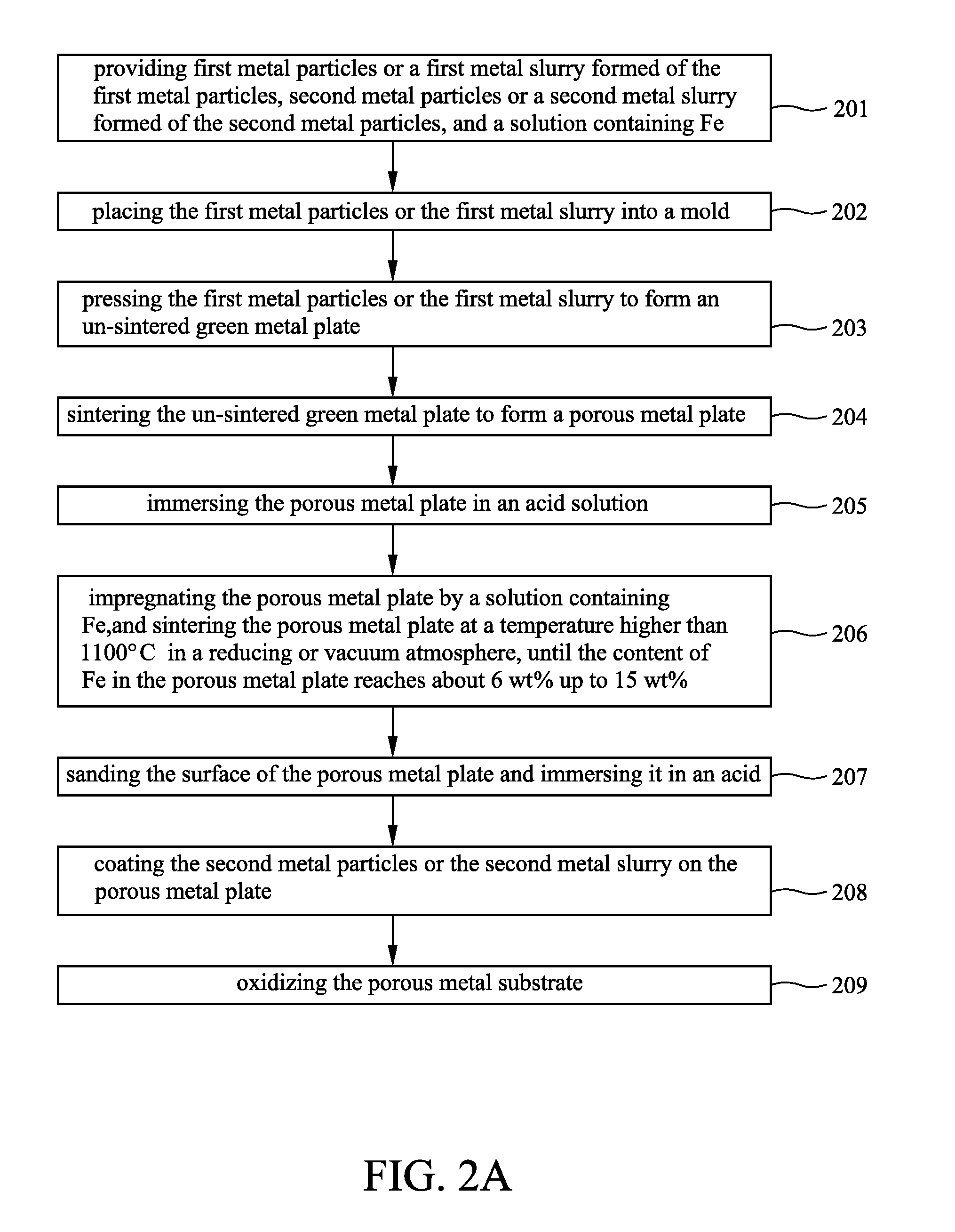
[0014]According to another aspect of the present disclosure, another embodiment provides a method for fabricating a porous metal substrate structure to support functional layers of a SOFC comprising: providing first metal particles or a first metal slurry formed of the first metal particles, second metal particles or a second metal slurry formed of the second metal particles, and a solution containing Fe, wherein the first metal particle has a size more than the second metal particle; forming a porous metal plate with the first metal particles or the first metal slurry by a sintering process; impregnating the solution containing Fe into the porous metal plate by a vacuum means, and then sintering the impregnated porous metal plate at a temperature higher than 1100° C. in a reducing or vacuum atmosphere, until the content of Fe in the porous metal plate reaches about from 6 wt % to 15 wt %; sanding and acid eroding surface of the porous metal plate; coating the second metal particles on the porous metal plate by a powder covering means or pasting the second metal slurry on the porous metal plate, and then sintering the second metal particles or the dried second metal slurry onto the porous metal plate at a temperature higher than 1100° C. to form a porous metal film on the porous metal plate; forming a porous metal substrate with the Fe impregnated porous metal plate and the porous metal film, and acid eroding the porous metal substrate so as to increase its gas permeability to be larger than 3 Darcy; and oxidizing the porous metal substrate so as to shrink its pore sizes.

Problems solved by technology

However, the catalytic conversion efficiency of LSCM is less than that of Ni and also LSCM is not a good conductor for oxygen (O) ions, therefore, the polarization resistance of LSCM anode is not low enough.

Method used


Image

  • Porous metal substrate structure for a solid oxide fuel cell
  • Porous metal substrate structure for a solid oxide fuel cell
  • Porous metal substrate structure for a solid oxide fuel cell

Examples


Embodiment Construction

[0022]For further understanding and recognizing the fulfilled functions and structural characteristics of the disclosure, several exemplary embodiments cooperating with detailed description are presented as the following.

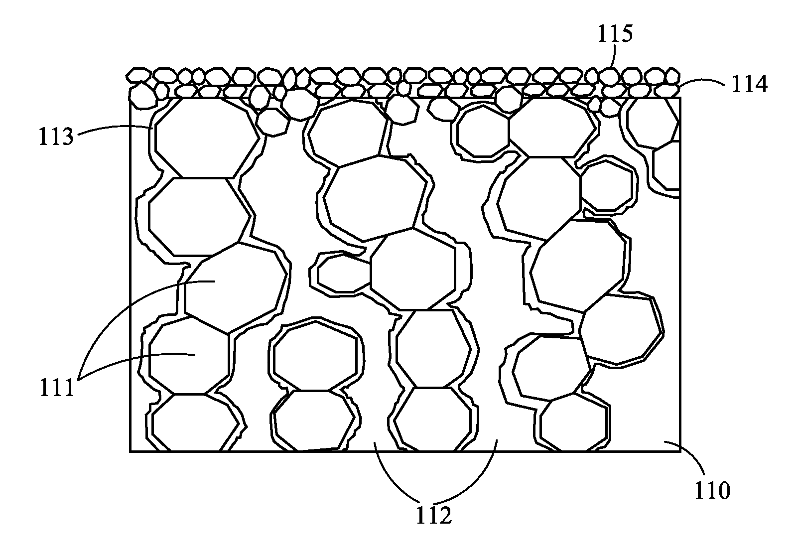
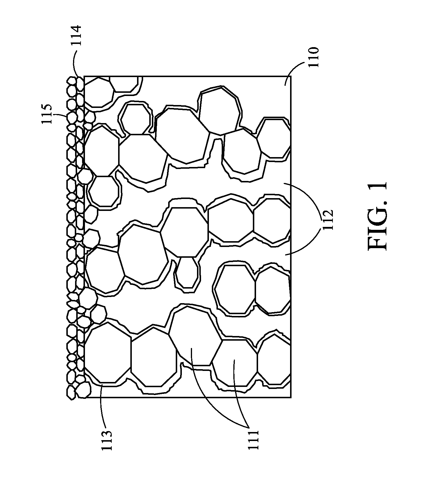
[0023]Please refer to FIG. 1, which is a schematic diagram showing the architecture of a porous metal substrate structure for supporting the functional layer of a SOFC according to an embodiment of the present disclosure. The porous metal substrate 100 is composed of a porous metal plate 110 and a porous metal film 114, wherein the porous metal plate 110 comprises first metal particles 111, gas channels 112, and a porous shell 113. The first metal particles 111 are composed of a first Ni—Fe mixture. The gas channels 112 are the gaps between the first metal particles 111, whereby gas is able to permeate though the porous metal substrate 100. The porous shell 113 is formed on the surface of each of the first metal particles 111. The porous shell 113 contains a third N...


PUM

PropertyMeasurementUnit
Temperatureaaaaaaaaaa
Thicknessaaaaaaaaaa

Abstract

The disclosure provides a porous metal substrate structure with high gas permeability and redox stability for a SOFC and the fabrication process thereof, the porous metal substrate structure comprising: a porous metal plate composed of first metal particles; and a porous metal film composed of second metal particles and formed on the porous metal plate; wherein the porous metal plate has a thickness more than the porous metal film, and the first metal particle has a size more than the second metal particle. Further, a porous shell containing Fe is formed on the surface of each metal particle by impregnating a solution containing Fe in a high temperature sintering process of reducing or vacuum atmosphere, and the oxidation and reduction processes. The substrate uses the porous shells containing Fe particles to absorb the leakage oxygen.

Description

CROSS-REFERENCE TO RELATED APPLICATIONS[0001]This non-provisional application claims priority under 35 U.S.C. §119(a) on Patent Application No. 099124324 filed in Taiwan (R.O.C.) on Jul. 23, 2010, the entire contents of which are hereby incorporated by reference.TECHNICAL FIELD[0002]The present disclosure relates to a solid oxide fuel cell (SOFC), and more particularly, to a porous metal substrate structure for a SOFC.TECHNICAL BACKGROUND[0003]Recently the solid oxide fuel cell (SOFC) has been a promising means of converting chemical energy into electrical energy by an electro-chemical mechanism.[0004]Usually in the conventional SOFC, the Yttria Stabilized Zirconia (YSZ) is used as the electrolyte, the cermet composed of nickel (Ni) and YSZ is used as the anode, and the perovskite composed of LaMnO3 is used as the cathode.[0005]When the SOFC works in a high-temperature environment, the anode fuel, H2, may somehow be suddenly interrupted, such that the air may get into the anode of t...

Claims


Application Information

Patent Timeline
IPC IPC(8): H01M4/64H01M4/90H01M4/88H01M8/12
CPCC04B35/47C04B2235/3225C04B2235/3227Y02E60/525H01M2008/1293Y02E60/521H01M8/1226Y02E60/50B22F3/1017B22F3/114B22F3/1143B22F3/26B22F5/006B22F5/10B22F2003/241B22F2201/20B22F2301/35B22F2998/10
Inventor HWANG, CHANG-SINGTSAI, CHUN-HUANGYU, JEN-FENGCHANG, CHUN-LIANGLIN, JUN-MENGCHENG, SHIH-WEI
Owner INST NUCLEAR ENERGY RES ROCAEC
Learn More