Thermoconductive composition, heat dissipating plate, heat dissipating substrate and circuit module using thermoconductive composition, and process for production of thermoconductive composition

a technology of thermoconductive composition and composition, which is applied in the direction of resistive material coating, solid-state devices, synthetic resin layered products, etc., can solve the problems of thermal conductivity, low formability, and large roughness of thermally conductive composition, so as to improve the heat dissipation performance or convenience, improve the adhesiveness between the composition and the metallic plate, and improve the wettability

Inactive Publication Date: 2012-02-02
PANASONIC CORP
View PDF2 Cites 12 Cited by
  • Summary
  • Abstract
  • Description
  • Claims
  • Application Information

AI Technical Summary

Benefits of technology

[0020]The invention is also a heat dissipating plate wherein the above-mentioned thermally conductive composition is fixed to a metallic plate. Moreover, the invention is a circuit module wherein this heat dissipating plate is used to fix a heat generating component to the thermally conductive composition, and further a circuit substrate is fixed to the metallic plate and connected to the heat generating component. Furthermore, the invention is a heat dissipating substrate wherein the thermally conductive composition is fixed to a metallic plate, and a wiring is fixed to the thermally conductive composition. Additionally, the invention is a circuit module wherein this heat dissipating substrate is used to fix a heat generating component to the thermally conductive composition and further connect the heat generating component to a wiring, and additionally a circuit substrate is fixed to the wiring. In any one of these articles, the thermally conductive composition of the invention is used, thereby making it possible to considerably improve the heat dissipating performance or convenience. Moreover, the wettability between the thermally conductive composition and any one of the metallic plates can be made high so that the adhesiveness between the composition and the metallic plate can be improved.

Problems solved by technology

However, conventional thermally conductive compositions each produced by adding an inorganic filler to a resin have the following problems: when the content by percentage of the inorganic filler in the thermally conductive composition is high, the thermal conductivity is increased; however, the surface roughness of the thermally conductive composition becomes large and the formability thereof becomes low; and furthermore, the gloss of any surface of the thermally conductive composition lowers, and voids or the like increase in the surface or inside the composition.
The problems are more easily caused as the content by percentage of the inorganic filler is made larger.
Moreover, the inorganic filler itself gets low in cohesive force, or the inorganic filler exposed to the surface drop out easily.
For this reason, even the fixation of electronic components and others onto the surface of the thermally conductive composition becomes difficult.
If the volume fraction of the inorganic filler is, for example, over 66% by volume, it is very difficult to subject the thermally conductive composition to shaping or some other treatment.
However, the surface roughness of the surfaces of the grains, which are actually shaped grains, abruptly becomes large so that the glossiness decreases abruptly.
Moreover, the adhesiveness thereof onto a heat generator declines so that the thermal conductivity may lower.
Alternatively, thermally conductive composition 7 itself gets brittle to be easily cracked.
As the crystallization rate of the crystalline resin is made higher, a substrate obtained therefrom is harder and more brittle.
In other words, the substrate is not bent but broken, or is easily chipped or cracked.
Thus, even when a crystalline resin is used to produce a heat dissipating substrate on which electronic components are to be mounted, the usage thereof is largely limited.
Even when an epoxy resin having mesogen groups is used, it is difficult to solve the problem described with reference to FIG. 34.
As the epoxy resin is further crystallized, the problem described with reference to FIG. 34 may be more easily caused.
Furthermore, such problems are easily caused from regions in which the content by percentage of an inorganic filler is lower than 66% by volume.
However, in the case of a crystalline epoxy resin, the crystallinity thereof is inhibited when three-dimensional bonds are formed.
As a result, a high thermal conductivity is not obtained in many cases.
Furthermore, a substrate in which a crystalline resin is used has a tendency that the substrate is hard and brittle, is not bent but broken, and is easily chipped or cracked.
Thus, when a heat dissipating substrate is produced by use of a crystalline resin, there may remain a problem for impact resistance in a drop test or other tests.

Method used


Image

  • Thermoconductive composition, heat dissipating plate, heat dissipating substrate and circuit module using thermoconductive composition, and process for production of thermoconductive composition
  • Thermoconductive composition, heat dissipating plate, heat dissipating substrate and circuit module using thermoconductive composition, and process for production of thermoconductive composition
  • Thermoconductive composition, heat dissipating plate, heat dissipating substrate and circuit module using thermoconductive composition, and process for production of thermoconductive composition

Examples


embodiment 1

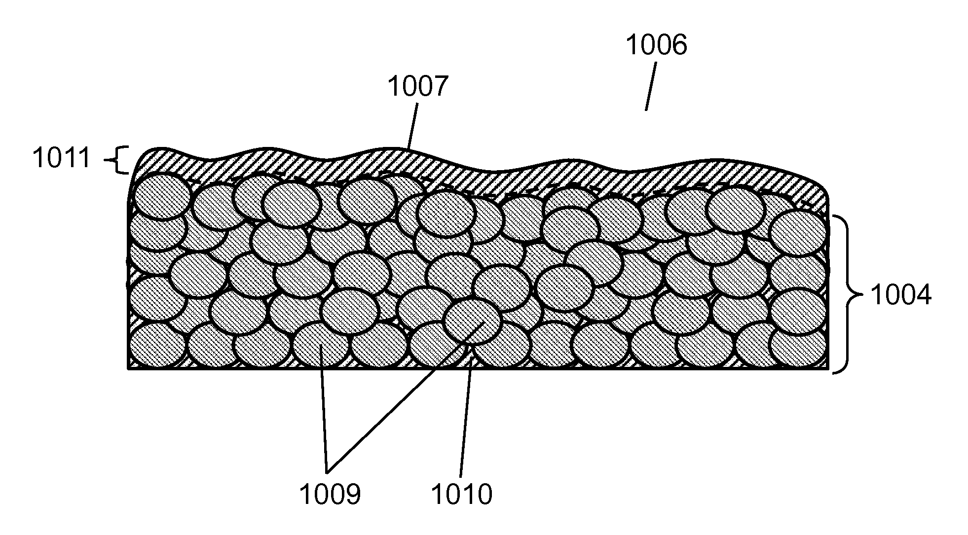
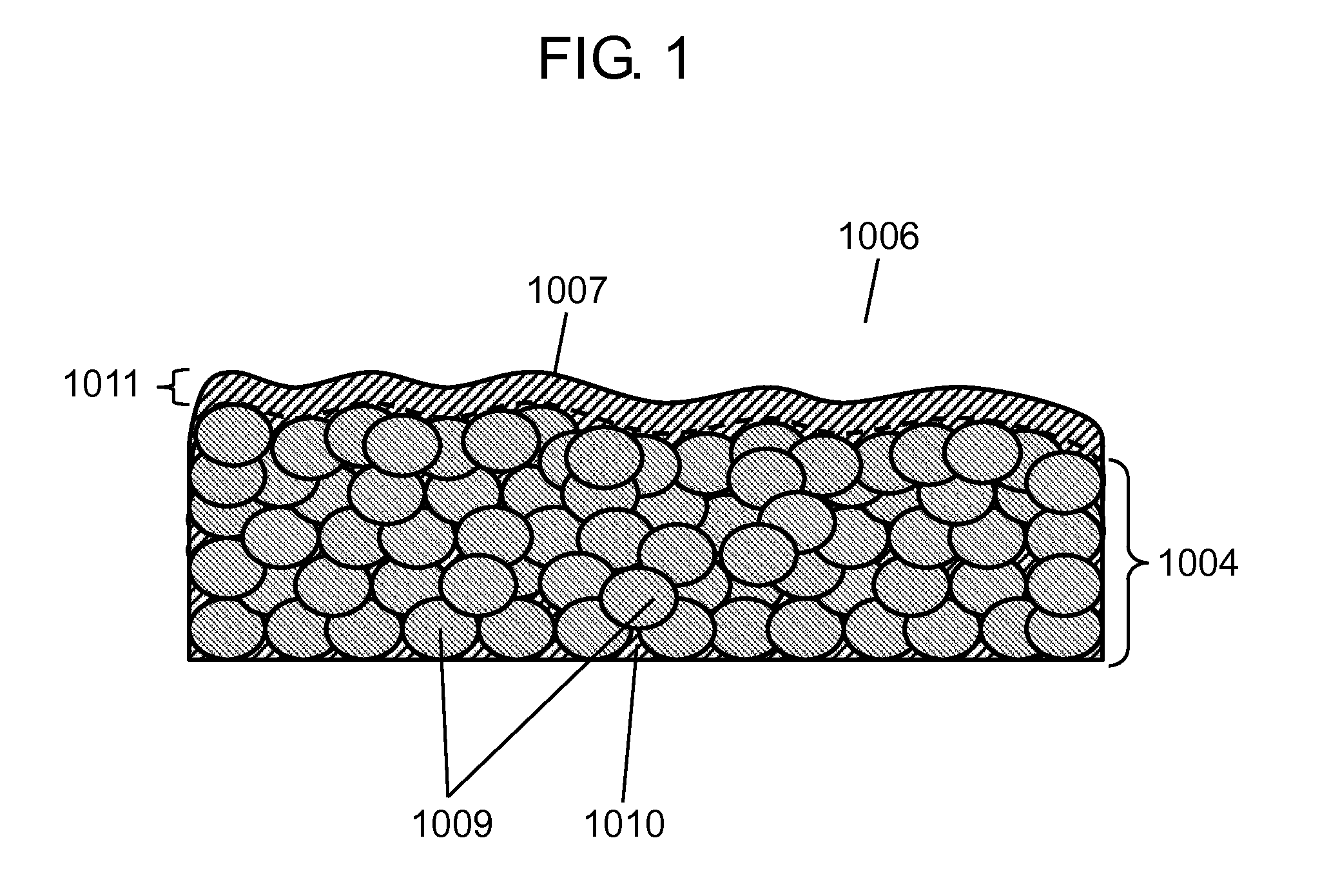
[0080]FIG. 1 is a sectional view of a thermally conductive composition in embodiment 1 of the invention.

[0081]Thermally conductive composition 1006 contains thermosetting resin 1010 containing a crystalline epoxy resin, and inorganic filler 1009. Inorganic filler 1009 is contained mainly in main portion 1004. On main portion 1004 is formed surface layer portion 1011 made only of thermosetting resin 1010, or made mainly of thermosetting resin 1010. In FIG. 1, a broken line is shown to distinguish main portion 1004 and surface layer portion 1011 from each other for the sake of convenience. However, a clear interface does not exist between the two, so that main portion 1004 and surface layer portion 1011 are formed to be continuous to each other. In this manner, thermally conductive composition 1006 also contains surface layer portion 1011 formed into a surface layer. In other words, surface layer portion 1011, inorganic filler 1009 and thermosetting resin 1010 each constitute a partia...

embodiment 2

[0198]With reference to FIG. 6, a heat dissipating plate according to an embodiment of the invention will be described hereinafter.

[0199]FIG. 6 is a sectional view of the heat dissipating plate according to the embodiment. Heat dissipating plate 1013 has metallic plate 1012 and sheet-form thermally conductive composition 1006 laid thereon. When the thickness of thermally conductive composition 1006 is set to 0.6 mm or more, reinforced electric insulation can be satisfied. The reinforced electric insulation means a single insulation for making a protection equivalent to or larger than a double insulation against electrocution. The double insulation is composed of a basic insulation and an additional insulation. When the reinforced electric insulation is satisfied as described above, the heat dissipating plate can satisfy the product-safety known in the UL standards, the IEC standards, and others, so that a primary-side electric circuit (for example, a power source circuit) can be for...

embodiment 3

[0231]The following will describe a circuit module of an embodiment of the invention with reference to FIGS. 12 to 15.

[0232]FIG. 12 is a sectional view for describing a situation that heat generating component 1014 is fixed on heat dissipating plate 1013 described with reference to FIG. 6. Heat generating component 1014 corresponds to, for example, an electronic component such as a transformer, a coil or a choke coil, or a light emitting element such as an LED or a semiconductor laser, as well as a power semiconductor (a power transistor, a power FET, a power transistor, a high-power LED, or a high-power laser). In order to fix heat generating component 1014 onto free surface 1007 of thermally conductive composition 1006, a thermally conductive adhesive or the like may be used. As has been described with reference to FIGS. 5A and 5B, free surface 1007 may be processed to form processed surface 1015.

[0233]The surface roughness of processed surface 1015 illustrated in FIG. 5B is desir...


PUM

PropertyMeasurementUnit
volume fractionaaaaaaaaaa

Abstract

A thermally conductive composition is made to contain a cured thermosetting resin containing a crystalline epoxy resin component, and an inorganic filler. The content by percentage of the inorganic filler in the thermally conductive composition is 66% or more and 90% or less by volume. This thermally conductive composition has a main portion made mainly of the inorganic filler, and a surface layer portion made mainly of the crystalline epoxy component and formed on the main portion to be continuous to the main portion.

Description

[0001]This application is a U.S. National Phase Application of PCT International Application PCT / JP2010 / 001171.TECHNICAL FIELD[0002]The present invention relates to a thermally conductive composition which is used in various components for which heat dissipation (heat radiation) is required, a heat dissipating plate, a heat dissipating substrate, and a circuit module each using this composition, and a process for producing the thermally conductive composition.BACKGROUND ART[0003]In order to make the size of electronic instruments small, the heat generation density of power semiconductors, high-functional semiconductors, light emitting elements, and others has been increasing. For the heat dissipation of such electronic components, thermally conductive compositions are used. However, conventional thermally conductive compositions each produced by adding an inorganic filler to a resin have the following problems: when the content by percentage of the inorganic filler in the thermally ...

Claims


Application Information

Patent Timeline
Patent Type & Authority Applications(United States)
IPC IPC(8): C09K5/14C08L63/00C08L33/00
CPCC08G59/64Y10T428/254C08L55/04C08L63/00C09K5/14H01L23/3735H01L23/3737H01L23/49861H05K1/0373H05K1/056H05K3/202H05K2201/0209H05K2201/09118C08K3/0033Y10T428/24917Y10T428/25Y10T428/31511H01L2924/0002Y10T428/31529C08L2666/24H01L2924/00C08K3/013
Inventor ASAHI, TOSHIYUKISHIMASAKI, YUKIHIROSHIMOYAMA, KOJI
Owner PANASONIC CORP
Why Eureka
Try Eureka