Battery Pack Configuration to Reduce Hazards Associated with Internal Short Circuits

a battery pack and short circuit technology, applied in the field of battery packs, can solve the problems of specialized handling and operating requirements, increased reaction rate and heat generation, and increased so as to minimize the risk of excessive heating and extensive collateral damage, the effect of minimizing the risk of initial thermal runaway events

Active Publication Date: 2012-02-09
TESLA INC
View PDF5 Cites 28 Cited by
  • Summary
  • Abstract
  • Description
  • Claims
  • Application Information

AI Technical Summary

Benefits of technology

[0013]The present invention provides a battery pack, or a battery pack module, that is configured to respond to a short circuit of moderate current in a manner that minimizes the risk of an initial thermal runaway event propagating throughout the battery pack / battery pack module. In general, the disclosed system allows pre-selection of which cell (or cells) of the cells comprising the battery pack / battery pack module will be the last cell(s) to respond to the short circuit. As a result, a thermal isolation barrier may be used to separate the preselected cell(s) from the other cells of the battery pack / battery pack module, thereby minimizing the risk of excessive heating and extensive collateral damage.

Problems solved by technology

This switch in drive train technology is not, however, without its technological hurdles as the use of an electric motor translates to the need for inexpensive batteries with high energy densities, long operating lifetimes, and operable in a wide range of conditions.
While current rechargeable battery technology is able to meet the demands of the automotive industry, the relatively unstable nature of the chemistries used in such batteries often leads to specialized handling and operating requirements.
For example, rechargeable batteries such as lithium-ion cells tend to be more prone to thermal runaway than primary cells, thermal runaway occurring when the internal reaction rate increases to the point that more heat is being generated than can be withdrawn, leading to a further increase in both reaction rate and heat generation.
Thermal runaway may be initiated by a short circuit within the cell, improper cell use, physical abuse, manufacturing defects, or exposure of the cell to extreme external temperatures.
In the case of a battery pack used in an electric vehicle, a severe car crash may simultaneously send multiple cells within the battery pack into thermal runaway.
Unfortunately, as fuse 101 is designed to prevent low resistance, high current shorts, it may not open and interrupt a sustained current of moderate magnitude such as that which may occur during an internal battery short.
Unfortunately if the temperature of the cell continues to increase, the material comprising the separator will completely melt and break-down, resulting in a massive internal short that can accelerate heating.
While individual cells may include one or more built-in safety mechanisms, as noted above, these safety mechanisms are not always effective when the cell is one of a large group of cells, i.e., the battery pack of FIG. 1.
For example, the CID within a cell typically has a relatively low voltage rating and therefore may be subject to arcing and fire when it attempts to open in a high voltage battery pack.
As a result, the cell may enter into a state of thermal runaway.
Additionally, due to the excessive heat generated by such an event, the temperature of adjacent cells within the battery pack will also increase, potentially leading to a cascading effect where the initiation of thermal runaway within a single cell propagates throughout the entire battery pack.
In such a situation, not only is power from the battery pack interrupted, but the system employing the battery pack is more likely to incur extensive collateral damage due to the scale of thermal runaway and the associated release of thermal energy.
While it is possible to design a battery pack that minimizes the risks of arcing or excessive heating, such an approach leads to increased cost, complexity and weight, all of which may be quite significant in a large battery pack such as that employed in a hybrid or an all-electric vehicle.

Method used


Image

  • Battery Pack Configuration to Reduce Hazards Associated with Internal Short Circuits
  • Battery Pack Configuration to Reduce Hazards Associated with Internal Short Circuits
  • Battery Pack Configuration to Reduce Hazards Associated with Internal Short Circuits

Examples


Embodiment Construction

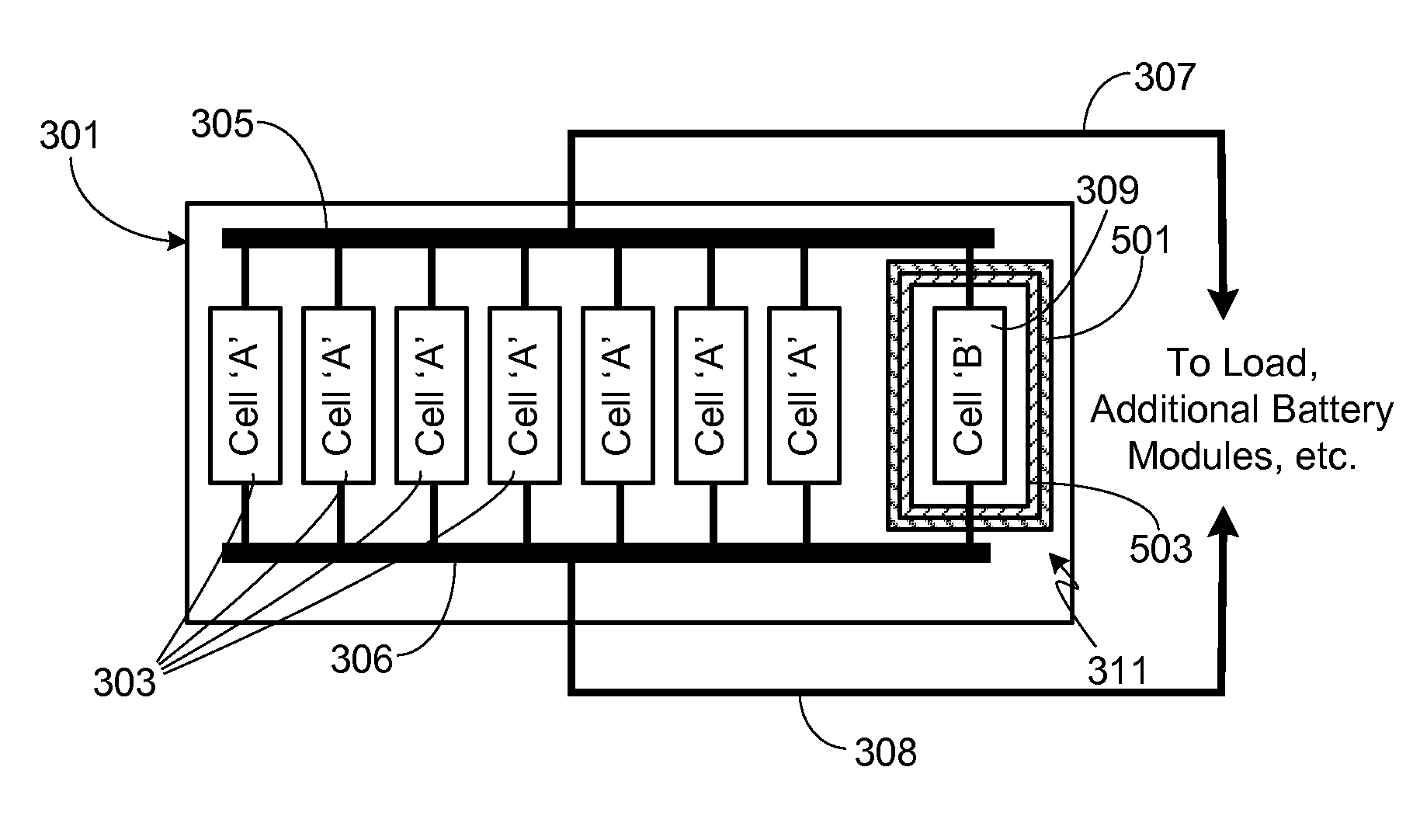
[0025]In the following text, the terms “battery”, “cell”, and “battery cell” may be used interchangeably and may refer to any of a variety of different cell types, chemistries and configurations including, but not limited to, lithium ion (e.g., lithium iron phosphate, lithium cobalt oxide, other lithium metal oxides, etc.), lithium ion polymer, nickel metal hydride, nickel cadmium, nickel hydrogen, nickel zinc, silver zinc, or other battery type / configuration. The term “battery pack” as used herein refers to multiple individual batteries electrically interconnected to achieve the desired voltage and capacity for a particular application, where the multiple batteries may be contained within a single piece or multi-piece housing. It should be understood that identical element symbols used on multiple figures refer to the same component, or components of equal functionality. Additionally, the accompanying figures are only meant to illustrate, not limit, the scope of the invention and s...


PUM

PropertyMeasurementUnit
temperatureaaaaaaaaaa
voltageaaaaaaaaaa

Abstract

A battery pack, or battery pack module, is provided that is configured to respond to a short circuit of moderate current in a manner that minimizes the risk of an initial thermal runaway event propagating throughout the battery pack / battery pack module. In general, the battery pack / battery module allows pre-selection of which cell of the cells comprising the battery pack / battery pack module will be the last cell to respond to the short circuit. As a result, a thermal isolation barrier may be used to separate the preselected cell from the other cells of the battery pack / battery pack module, thereby minimizing the risk of excessive heating and extensive collateral damage.

Description

CROSS-REFERENCES TO RELATED APPLICATIONS[0001]This application is a continuation-in-part of U.S. patent application Ser. No. 12 / 850,282, filed Aug. 4, 2010, the disclosure of which is incorporated herein by reference for any and all purposes.FIELD OF THE INVENTION[0002]The present invention relates generally to battery packs and, more particularly, to a battery pack that is designed to mitigate the effects of arcing due to an internal short circuit.BACKGROUND OF THE INVENTION[0003]There is currently a trend in the automotive industry to replace combustion engines with electric motors or a combination of an electric motor and a combustion engine, thereby substantially reducing the environmental impact of automobiles by reducing (i.e., hybrids) or completely eliminating (i.e., electric vehicles) car emissions. This switch in drive train technology is not, however, without its technological hurdles as the use of an electric motor translates to the need for inexpensive batteries with hi...

Claims


Application Information

Patent Timeline
Patent Type & Authority Applications(United States)
IPC IPC(8): H01M10/50H01M2/22H01M50/528H01M50/574
CPCH01M2/34H01M2/348H01M10/5087H01M10/5016H01M10/5075H01M10/5004H01M10/625H01M10/6567H01M10/613H01M10/658Y02E60/10H01M50/581H01M50/574
Inventor HERMANN, WESTON ARTHURKOHN, SCOTT IRABECK, DAVID G.
Owner TESLA INC
Why Eureka
Try Eureka