Copper anode refining system and method

a copper anode and refining system technology, applied in the field of anodes, can solve the problems of high furnace refractory wear, and significant operational difficulties, and achieve the effect of reducing oxygen

Active Publication Date: 2012-02-16
PRAXAIR TECH INC
View PDF8 Cites 10 Cited by
  • Summary
  • Abstract
  • Description
  • Claims
  • Application Information

AI Technical Summary

Benefits of technology

[0007]In one aspect, the present invention may be characterized as a method for the refining of anode copper comprising the steps of: (i) providing molten blister copper to a furnace; (ii) charging copper scrap to the molten blister copper in the furnace; (iii) melting said copper scrap or heating the molten blister copper using a melting flame produced from a top blown, multi-functional coherent jet lance; (iv) oxidizing sulfur impurities in the molten blister copper in the furnace using a top-blown, coherent oxygen-containing gas stream ejected from the coherent jet lance, said coherent jet lance coupled to the oxygen-containing gas source and the fuel source; and (v) reducing oxygen in the molten blister copper in the furnace using a top-blown, coherent reducing gas stream containing a reducing agent and an inert gas ejected from the coherent jet lance.
[0008]In another aspect, the present invention may be characterized as a system for copper anode refining comprising: a copper metallurgical furnace having a refractory wall, the furnace adapted to contain a bath of molten copper having a top surface and said furnace defining a headspace above the top surface of the copper bath; at least one multi-functional, coherent jet lance connected to sources of oxygen-containing gas, inert gas, reducing agent and fuel, said coherent jet lance mounted in said furnace refractory wall at a

Problems solved by technology

However, numerous operational difficulties and significant costs are associated with conventional copper anode fire refining process and injection of the oxidant and reductant gas streams via submerged tuyeres.
Such d

Method used


Image

  • Copper anode refining system and method
  • Copper anode refining system and method
  • Copper anode refining system and method

Examples


examples

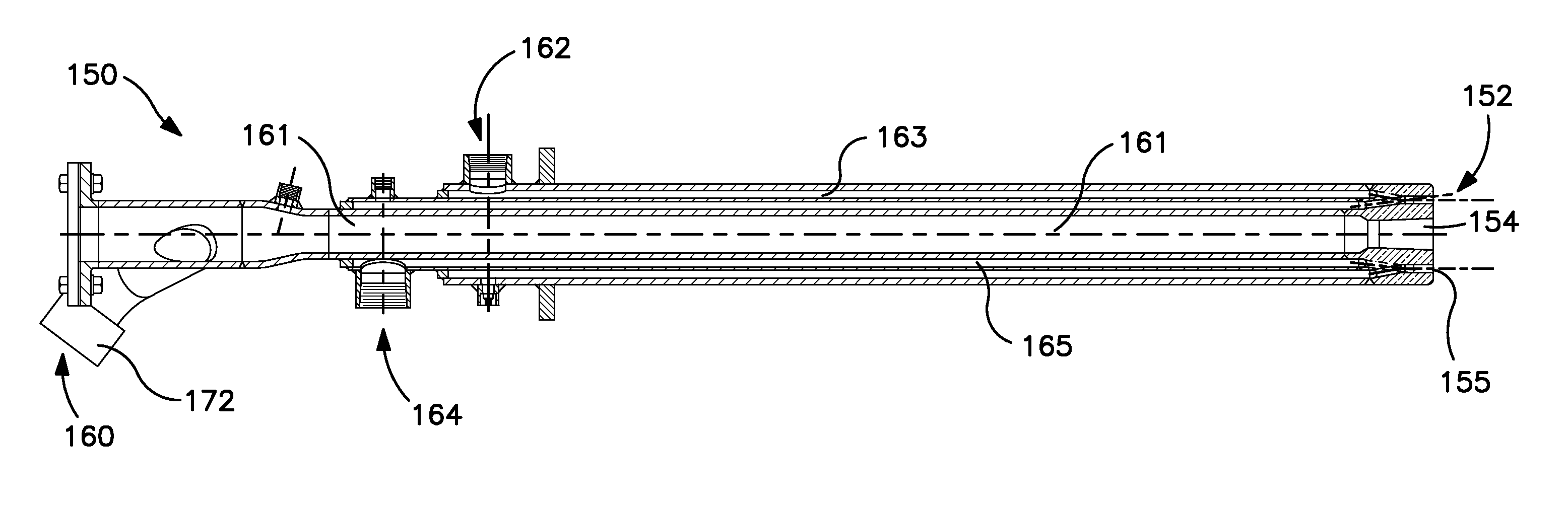
[0063]Table 1 depicts the ranges of gas flows contemplated for use with the present copper anode refining system and method for a commercial scale operation.

TABLE 1Typical Lance Assembly Gas FlowsChargingMeltingOxidationReductionHold / IdleBurnerRefiningRefiningGas Flows (SCFH)ModeModeModeModeSecondary Ports - OxygenPurge flow4700-9300~4000~4000Secondary Ports - Fuel (NG)Purge flow2500-5000~5000~5000Main Nozzle - Oxygen04600-9300~20000 to 300000Main Nozzle - Nitrogen~5000-100000~25000 to 35000~40000 to 55000Main Nozzle - Reduce Agent / Fuel02500-50000 ~5000 to 15000Main Nozzle - Oxygen / NGN / A 7100-14300N / AN / AMain Nozzle - Oxygen / NitrogenN / AN / A~45000 to 65000N / AMain Nozzle - NG / NitrogenN / AN / AN / A~45000 to 70000

[0064]The presently disclosed copper anode refining system and method was evaluated in an anode furnace of Kennecott Utah Copper, a commercial scale copper anode furnace. Comparative results showing the performance of the anode furnace using the present copper anode refining system a...


PUM

PropertyMeasurementUnit
Percent by volumeaaaaaaaaaa
Fractionaaaaaaaaaa
Fractionaaaaaaaaaa

Abstract

A method and system for the copper anode refining is provided in which coherent jet technology is employed to heat the molten blister copper and/or melt scrap copper charges using a melting flame, oxidize the sulfur in the molten blister copper, and reduce the oxygen in the molten blister copper using top-blown coherent jet gas streams from one or more multi-functional, coherent jet lance assemblies. The present system and method employs a microprocessor-based controller operatively controlling the flow of an oxygen-containing gas, an inert gas, a reducing agent and a fuel to the coherent jet lance. The disclosed copper anode refining system and method greatly improves copper production while lowering oxidation/reduction cycle times and minimizing NOx emissions.

Description

CROSS REFERENCE TO RELATED APPLICATIONS[0001]This patent application claims priority to U.S. provisional patent application Ser. No. 61 / 305,008 filed Feb. 16, 2010, the disclosure of which is incorporated by reference herein.FIELD OF THE INVENTION[0002]The present invention relates to the pyrometallurgical treatment of copper-containing materials with process gases, such as oxidizing and reducing process gases, to convert such materials to copper-containing materials of higher value. More particularly, the present invention relates to the anode refining of molten blister copper to remove sulfur, oxygen and other impurities by the selective treatment of the molten blister copper with coherent gas streams of oxidizing and reducing process gases.BACKGROUND[0003]The production of copper typically involves a multi-step procedure which includes concentration, smelting, converting, refining, anode casting and electrolytic refining procedures. Typically, starting with an ore comprising one ...

Claims


Application Information

Patent Timeline
IPC IPC(8): C22B15/14C22B5/00F27D99/00
CPCC21C5/4606C22B9/05C22B15/0036C22B15/006Y02P10/212F23D14/22F23D14/32F23D14/56F23C2900/07022Y02P10/20Y02P10/32C21C5/46C22B9/055Y02E20/34
Inventor GEORGE, DAVID B.ENRIQUEZ, JR., ARSENIO C.DENEYS, ADRIAN CHRISTIANMAHONEY, WILLIAM JOHNMASTERSON, IAN FRANCISMANLEY, STEPHENCATES, JESSEALBRECHT, KEVIN
Owner PRAXAIR TECH INC
Why Eureka
Try Eureka