Hydrogen concentration sensor utilizing cell voltage resulting from hydrogen partial pressure difference

a technology of hydrogen partial pressure and concentration sensor, which is applied in the direction of instruments, electrochemical generators, material analysis, etc., can solve the problems of fuel cell stack instability, failure, and relatively high manufacturing cost of meas, and achieve the effect of reducing the risk of failure, and increasing the damage of each even

Inactive Publication Date: 2012-02-16
GM GLOBAL TECH OPERATIONS LLC
View PDF3 Cites 4 Cited by
  • Summary
  • Abstract
  • Description
  • Claims
  • Application Information

AI Technical Summary

Benefits of technology

[0017]In accordance with the teachings of the present invention, a hydrogen concentration sensor is disclosed for measuring the hydrogen concentration in an anode sub-system of a fuel cell system. The hydrogen concentration sensor includes a membrane, a first catalyst layer on one side of the membrane and a second catalyst layer on an opposite side of the membrane where the sensor operates as a concentration cell. The first catalyst layer is exposed to fresh hydrogen for the anode side of a fuel cell stack and the second catalyst layer is exposed to an anode recirculation gas from an anode exhaust of the fuel cell stack. The voltage generated by the sensor allows the hydrogen partial pressure in the recirculation gas to be determined, from which the hydrogen concentration can be determined.

Problems solved by technology

MEAs are relatively expensive to manufacture and require certain conditions for effective operation.
Nitrogen in the anode side of the fuel cell stack dilutes the hydrogen such that if the nitrogen concentration increases beyond a certain percentage, such as 50%, the fuel cell stack becomes unstable and may fail.
Therefore, without accurately knowing the hydrogen concentration, each of these events will be more damaging than necessary.
However, known hydrogen estimation models have typically been relatively inaccurate due to increases in gas cross-over rate as the stack ages.
However, known hydrogen sensors of this type are susceptible to water droplets, which require liquid water separators in the exhaust in order to allow the sensors to operate properly.
Further, there is a measurement delay due to the volume the exhaust gas must travel to reach the sensor, which can be on the order of fifteen seconds.
This requires the use of significant plumbing and water separation devices that add volume to the system and generally provides an unacceptable time delay to the measurement.
These sensors also are fairly expensive where the system typically employs two sensors, one in the anode inlet manifold and one in the anode outlet manifold.
Because the nitrogen buildup typically occurs very rapidly at high power transients, which may be limited in time, the delay in the sensor reading may cause the hydrogen concentration measurement to not be available during the power up-transient when the nitrogen concentration is the highest.

Method used


Image

  • Hydrogen concentration sensor utilizing cell voltage resulting from hydrogen partial pressure difference
  • Hydrogen concentration sensor utilizing cell voltage resulting from hydrogen partial pressure difference
  • Hydrogen concentration sensor utilizing cell voltage resulting from hydrogen partial pressure difference

Examples


Embodiment Construction

[0023]The following discussion of the embodiments of the invention directed to a hydrogen concentration sensor for a fuel cell system is merely exemplary in nature, and is in no way intended to limit the invention or its applications or uses.

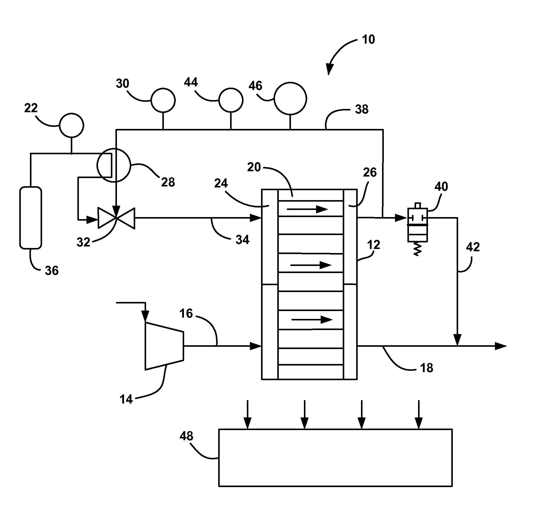
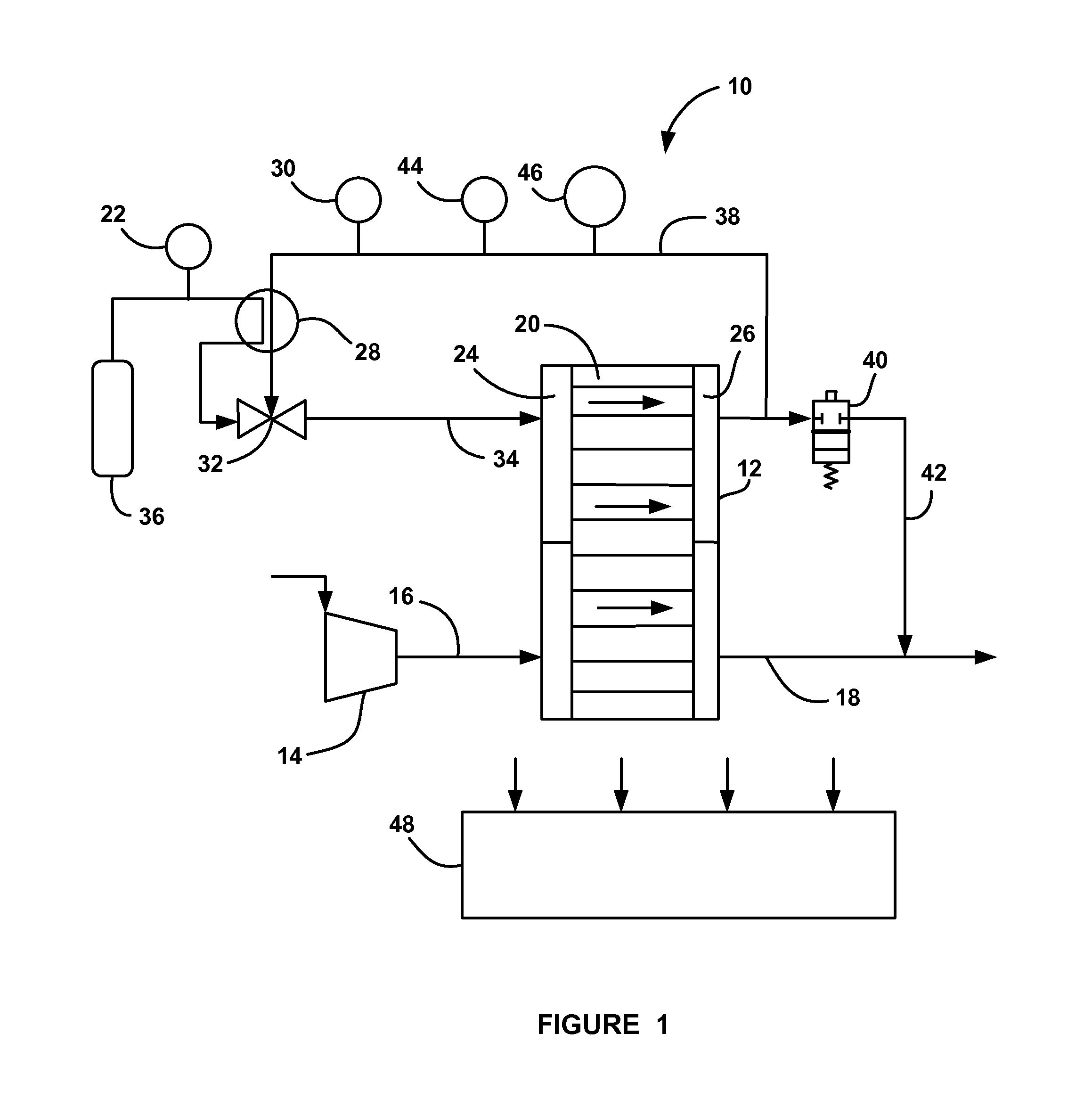
[0024]FIG. 1 is a schematic plan view of a fuel cell system 10 including a fuel cell stack 12 having fuel cells 20. A compressor 14 provides compressed air to the cathode side of the fuel cell stack 12 on a cathode input line 16. A cathode exhaust gas is output from the fuel cell stack 12 on a cathode exhaust gas line 18. An injector 32 injects hydrogen gas from a hydrogen source 36, such as a high pressure tank, into the anode side of the fuel cell stack 12 on an anode input line 34 through an anode inlet manifold 24. The fresh hydrogen from the source 36 is also sent through a hydrogen concentration sensor assembly 28, discussed in detail below. A pressure sensor 22 measures the pressure of the fresh hydrogen gas provided to the injector 32. A...


PUM

PropertyMeasurementUnit
thicknessaaaaaaaaaa
cell voltageaaaaaaaaaa
voltage potentialaaaaaaaaaa

Abstract

A hydrogen concentration sensor for measuring the hydrogen concentration in an anode sub-system of a fuel cell system. The hydrogen concentration sensor includes a membrane, a first catalyst layer on one side of the membrane and a second catalyst layer on an opposite side of the membrane where the sensor operates as a concentration cell. The first catalyst layer is exposed to fresh hydrogen for the anode side of a fuel cell stack and the second catalyst layer is exposed to an anode recirculation gas from an anode exhaust of the fuel cell stack. The voltage generated by the sensor allows the hydrogen partial pressure in the recirculation gas to be determined, from which the hydrogen concentration can be determined.

Description

BACKGROUND OF THE INVENTION[0001]1. Field of the Invention[0002]This invention relates generally to a hydrogen concentration sensor that determines the concentration of hydrogen in an anode sub-system of a fuel cell system and, more particularly, to a hydrogen concentration sensor that determines the concentration of hydrogen in an anode sub-system of a fuel cell system that employs anode exhaust gas recirculation, where the Nernst equation is used to determine the hydrogen partial pressure in the recirculation gas from the hydrogen concentration sensor voltage output and the hydrogen partial pressure is used to determine the hydrogen concentration in the recirculation gas.[0003]2. Discussion of the Related Art[0004]Hydrogen is a very attractive fuel because it is clean and can be used to efficiently produce electricity in a fuel cell. A hydrogen fuel cell is an electro-chemical device that includes an anode and a cathode with an electrolyte therebetween. The anode receives hydrogen...

Claims


Application Information

Patent Timeline
Patent Type & Authority Applications(United States)
IPC IPC(8): H01M8/04G01M15/10H01M8/24
CPCH01M8/04343H01M8/04388H01M8/04402Y02E60/50H01M8/04552H01M8/04798H01M8/04805H01M8/04514
Inventor MASLYN, ANDREW J.LAKSHMANAN, BALASUBRAMANIAN
Owner GM GLOBAL TECH OPERATIONS LLC
Why Eureka
Try Eureka