Vacuum heating device and vacuum heat treatment method

a vacuum heating device and heat treatment technology, applied in the field of vacuum heat treatment method, can solve problems such as service efficiency degradation, and achieve the effect of low resistan

a vacuum heating device and heat treatment technology, applied in the field of vacuum heat treatment method, can solve problems such as service efficiency degradation, and achieve the effect of low resistan

US20120045190A1Active Publication Date: 2012-02-23ULVAC INC

Image

  • Vacuum heating device and vacuum heat treatment method
  • Vacuum heating device and vacuum heat treatment method
  • Vacuum heating device and vacuum heat treatment method

Examples


Embodiment Construction

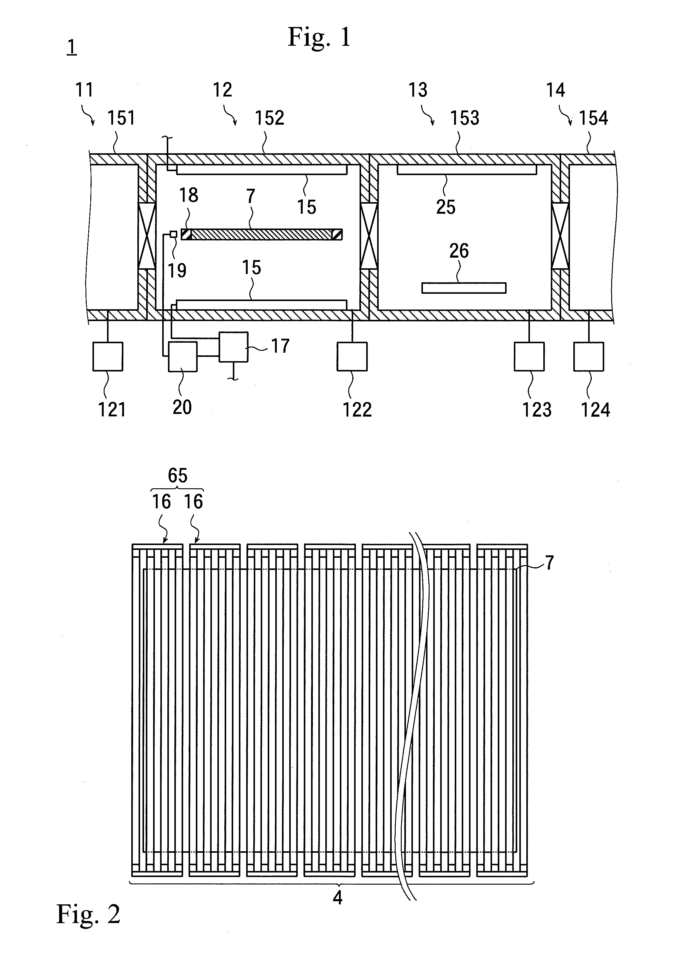
[0053]Reference numeral 1 of FIG. 1 generally shows a film forming apparatus, which has a carry-in unit 11, a heating unit 12, a processing unit 13, and a carry-out unit 14.

[0054]The units 11 to 14 have vacuum chambers 151 to 154, to which vacuum exhaust systems 121 to 124 are connected, respectively, so that each unit can be separately vacuum evacuated.

[0055]In the film forming apparatus 1, object to be processed (such as, semiconductor substrates or liquid crystal glass substrates or the like) is heated in a vacuum ambience in the vacuum chamber 152 of the heating unit 12, and then, a thin film is formed on the surface of the object to be processed in the vacuum chamber 153 of the processing unit 13.

[0056]Such a vacuum heat treatment method is hereinafter described. First, the vacuum chamber 152 of the heating unit 12 and the vacuum chamber 153 of the processing unit 13 are previously vacuum evacuated. Then, after an object to be processed is carried into the vacuum chamber 151 of...


PUM


Abstract

A uniform voltage is applied to loads even to other than a multiple of three loads made of heating lamps connected in parallel to each other, without causing any burden on a primary side. The number of loads is divided into a multiple of three and a multiple of two. A three-phase AC voltage is applied to three primary windings, which are connected as a Y-connection or a Δ-connection. Secondary windings, which are each magnetically coupled to a primary winding of a plurality of three-phase transformers and have the same number of turns, are connected with the multiple of three loads. The number of turns of the M-seat primary winding of a Scott transformer is divided into two at a midpoint, to which an end of the T-seat primary winding having a number of turns equal to (√3) / 2 times that of the M-seat primary winding, is connected and to which the three-phase AC voltage is applied. The M-seat primary winding and the T-seat primary winding in at least one Scott transformers are each magnetically coupled with each of the secondary windings having the same number of turns. The multiple of two loads are connected to the secondary windings so that no secondary windings appear without a load connected thereto. Thus, an AC voltage can be uniformly applied to the heating lamps without increasing any burden on the primary side.

Description

[0001]This application is a continuation of International Application No. PCT / JP2010 / 053042, filed on Feb. 26, 2010, which claims priority to Japan Patent Application No. 2009-046314, filed on Feb. 27, 2009. The contents of the prior applications are herein incorporated by reference in their entireties.BACKGROUND[0002]The present invention generally relates to a vacuum heat treatment method (such as, sputtering, vapor deposition, or etching) for processing an object to be processed in a vacuum ambience while heating the object to be processed, and in particular, to a technique for heating an object to be processed with a heating lamp.[0003]Objects to be processed (such as, semiconductor wafers or liquid-crystal glass substrates) have been processed by sputtering or vapor deposition so as to form thin films thereon or to pattern thin films on the object to be processed by etching or the like.[0004]When such a processing is performed, the objects to be processed are heated for vacuum ...

Claims


Application Information

Patent Timeline
23 Feb 2012
Publication
US20120045190A1
IPC
H05B37/00; H05B1/00
CPC
H02M5/257; H01L21/67115; H01L21/26
Inventors
YOSHIMOTO, TSUYOSHI; YAMANE, KATSUMI