Microplasma generator and methods therefor

a microplasma and generator technology, applied in the field of microplasma generators and methods therefor, can solve the problems of not being able to produce not being able to meet the needs of a single large diode, etc., to achieve the effect of low cos

Active Publication Date: 2012-02-23
TRUSTEES OF TUFTS COLLEGE TUFTS UNIV
View PDF4 Cites 30 Cited by
  • Summary
  • Abstract
  • Description
  • Claims
  • Application Information

AI Technical Summary

Benefits of technology

[0009]In certain methods and systems of the invention, the microplasma generator of the invention is used to deposit materials on a substrate in a “roll-to-roll coating” process. The substrate material can be supplied in a roll form, and the rolled substrate material is unrolled, processed by the microplasma generator, which is preferably a microplasma array that produces a linear plasma, and the substrate is then re-rolled. The substrate can be processed by depositing a thin film coatin

Problems solved by technology

PV devices are not yet cost competitive with fossil fuels.
The technologies developed to create 108 transistor chips are not necessarily well-suited to th

Method used


Image

  • Microplasma generator and methods therefor
  • Microplasma generator and methods therefor
  • Microplasma generator and methods therefor

Examples


Embodiment Construction

[0031]This application claims the benefit of U.S. Provisional Application No. 61 / 173,334, filed Apr. 28, 2009, the entire contents of which are incorporated herein by reference.

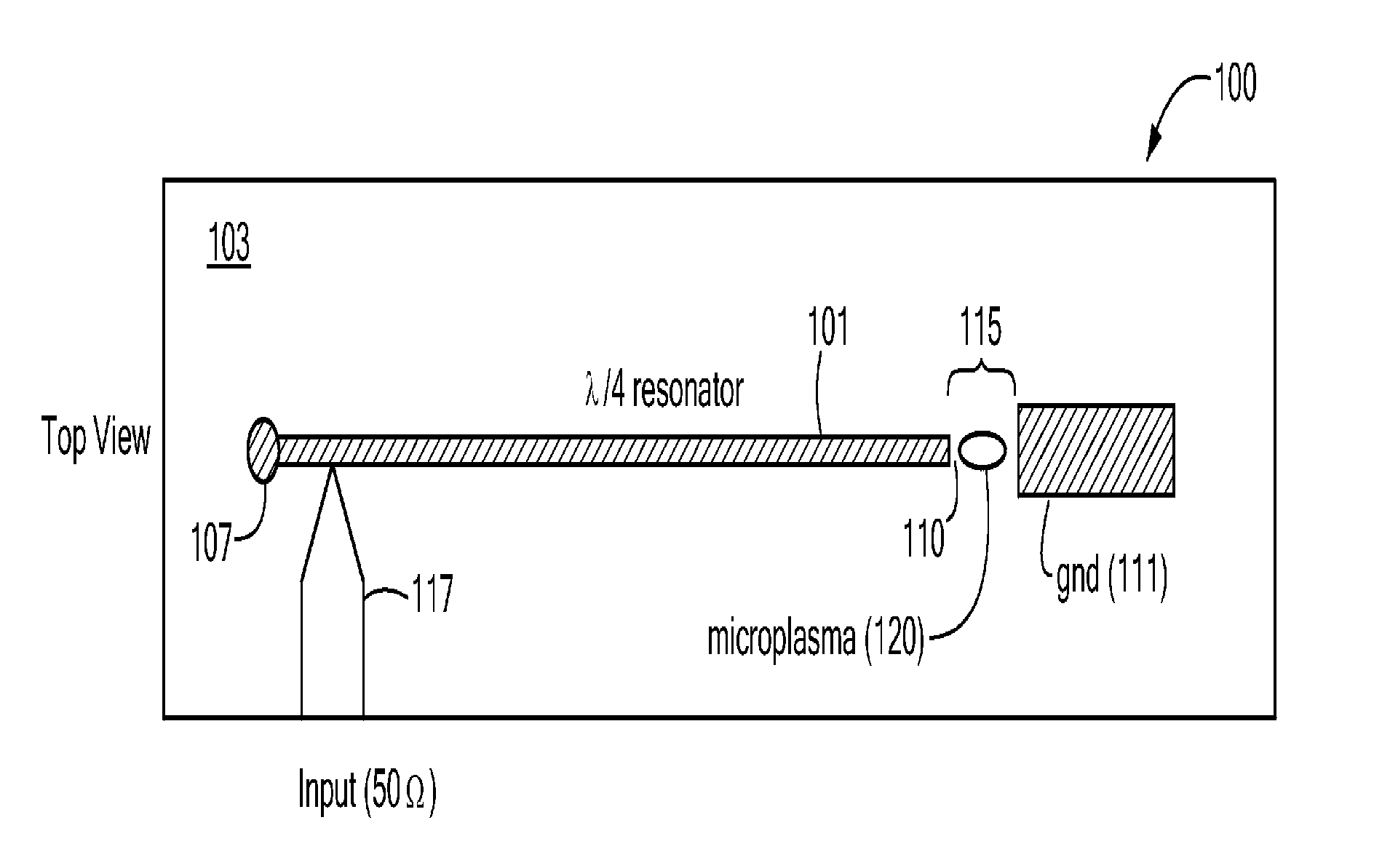
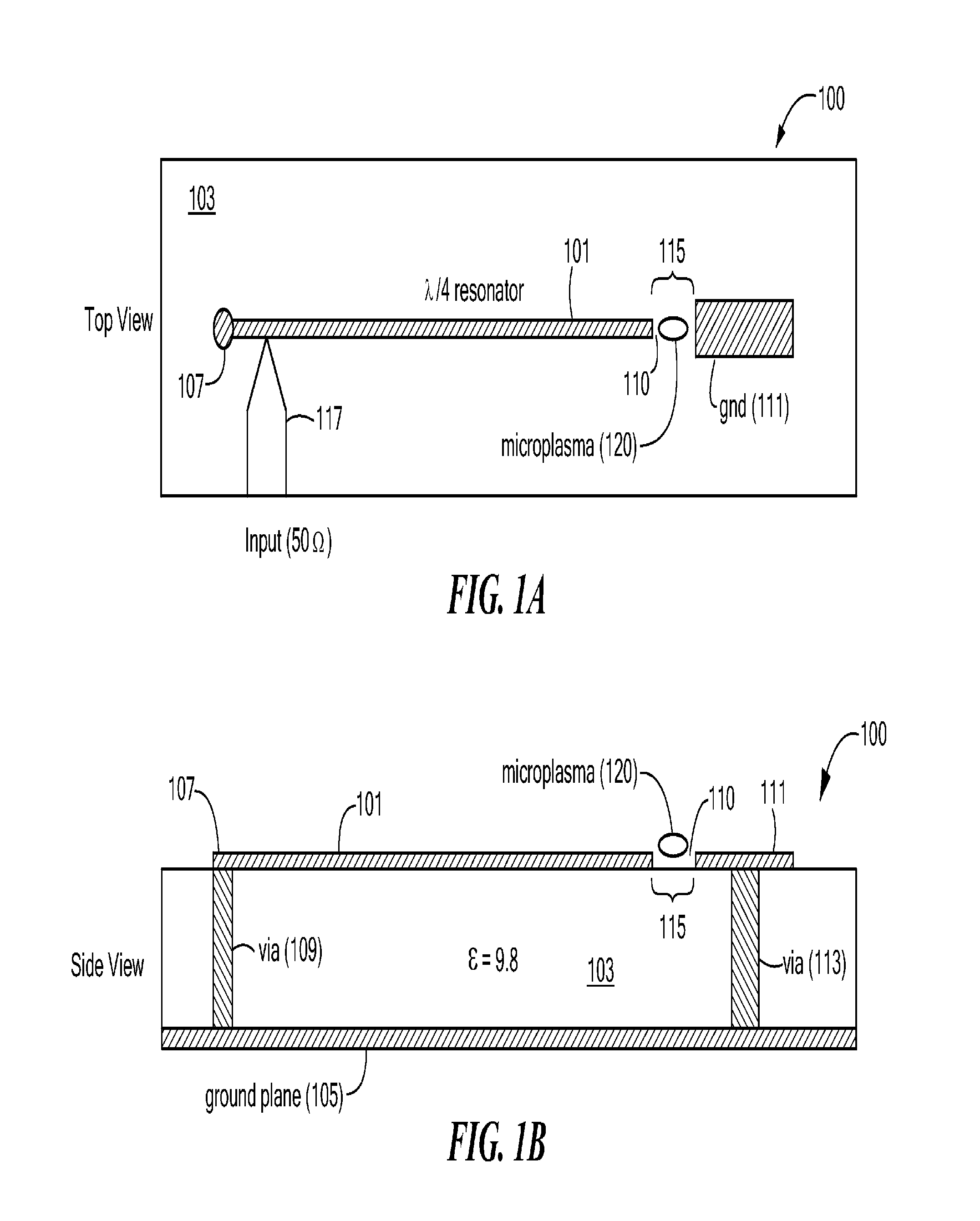
[0032]FIGS. 1A and 1B illustrate top and side cross-section views, respectively, of a microplasma generator 100 according to one aspect of the invention. The generator 100 in this embodiment comprises a single strip of metal 101 supported on the surface of a dielectric material 103. A ground plane 105 is provided on the dielectric material 103, opposite the metal strip 101. A first end 107 of the metal strip 101 is connected to the ground plane 105 through a via 109 in the dielectric material 103. A ground electrode 111 is connected to the ground plane 105 through via 113. A gap 115 is defined in the area between the second end 110 of the metal strip 101 and the ground electrode 111.

[0033]A source 117 of high frequency power is connected to the strip 101, preferably at a location on the strip where the input ...


PUM

PropertyMeasurementUnit
Temperatureaaaaaaaaaa
Lengthaaaaaaaaaa

Abstract

A low-temperature, atmospheric-pressure microplasma generator comprises at least one strip of metal on a dielectric substrate. A first end of the strip is connected to a ground plane and the second end of the strip is adjacent to a grounded electrode, with a gap being defined between the second end of the strip and the grounded electrode. High frequency power is supplied to the strip. The frequency is selected so that the length of the strip is an odd integer multiple of ¼ of the wavelength traveling on the strip. A microplasma forms in the gap between the second end of the strip and the grounded electrode due to electric fields in that region. A microplasma generator array comprises a plurality of strongly-coupled resonant strips in close proximity to one another. At least one of the strips has an input for high-frequency electrical power. The remaining strips resonate due to coupling from the at least one powered strip. The array can provide a continuous line or ring of plasma. The microplasma generator can be used to alter the surface of a substrate, such as by adding material (deposition), removal of material (etching), or modifying surface chemistry.

Description

CROSS-REFERENCE TO RELATED APPLICATION[0001]This application claims the benefit of U.S. Provisional Application No. 61 / 173,334, filed Apr. 28, 2009.STATEMENT REGARDING FEDERALLY SPONSORED RESEARCH OR DEVELOPMENT[0002]The invention was made with support from Grant DE-SC0001923 from the U.S. Department of Energy. The United States Government has certain rights in the invention.BACKGROUND OF THE INVENTION[0003]There is a need for improved technologies for processing the surfaces of substrates. Photovoltaic (PV) devices, for example, are typically fabricated by depositing thin film layers of various materials, such as silicon and metal, on a substrate material, such as a glass sheet, to form a solar cell.[0004]PV devices are not yet cost competitive with fossil fuels. Currently, the manufacturing of PV devices is based on technologies originally developed by the semiconductor industry. Semiconductor chips are extremely sophisticated, but have a small area (˜1 cm2). By contrast, photovol...

Claims


Application Information

Patent Timeline
IPC IPC(8): H01J19/80H01L31/18C23C16/50
CPCC23C16/24C23C16/511C23C16/545H01J37/32366H05H2001/4622H01L31/1876Y02E10/50H05H1/46H01J37/32825Y02P70/50H05H1/4622H01L31/18H01L31/04
Inventor HOPWOOD, JEFFREY A.
Owner TRUSTEES OF TUFTS COLLEGE TUFTS UNIV
Why Eureka
Try Eureka