Temperature adjusting device and an intelligent temperature control method for a sand and dust environment testing system

a technology of environmental testing and temperature control, applied in the direction of temperatue control, process and machine control, instruments, etc., can solve the problems of long time required for cooling water, inconvenient cleaning, and more complex structure, and achieve convenient cleaning, high equipment utilization efficiency, and compact structure

Inactive Publication Date: 2012-03-01
BEIHANG UNIV
View PDF6 Cites 19 Cited by
  • Summary
  • Abstract
  • Description
  • Claims
  • Application Information

AI Technical Summary

Benefits of technology

[0015]3) realize the temperature control of the airflow in the circulating air duct by means of the separators, guide vanes and contractions section existing in the circulating air duct, and provide a temperature adjusting system featuring compact structure, easy cleaning and high equipment utilization efficiency.

Problems solved by technology

1. With the big air-conditioner 2 and the small air-conditioner 3 for controlling the temperature of the wind tunnel, the system features a more complex structure and more space occupied. The inlet duct 7 of the big air-conditioner, the inlet duct 8 of the small air-conditioner and the return-air duct 9 of the air-conditioner directly intercommunicate with the circulating duct. As a result, the airflow quality in the air duct 1 is influenced by ducts 7, 8 and 9.
2. To realize the temperature control, the circular cooling water and chilled water from the water source 10 of the cold-water unit are used as cooling medium. Moreover, the electric heater 5 and variable-frequency & speed-regulation blower 6 accommodated in the small air-conditioner coordinate with each other to fulfill the temperature-adjusting task under different working conditions and heat loads. The cooling working medium realizes cooling by flowing through the finned pipe 4 of the surface cooler and realizes heating by flowing through the electric heater 5. Since the flowing air contains sand and dust, when passing through the finned pipe 4 of the surface cooler and the fin-type electric heater 5, the dust will accumulate on them and the heat transfer will be influenced. In this way, extra compressed air blow-off ducts 11 and 12 are required, but this causes inconvenience in cleaning.
3. The circulating air duct 1 adopts external heat insulation structure. When conducting a low-temperature test after the implementation of a high-temperature test, a long time is required for cooling the water since the heat transfer area of the surface cooler 4 is limited. Consequently, the utilization efficiency of the test device system is seriously affected.
However, this method enlarges the variation range of the temperature difference and increases the control difficulty.
At the same time, as the temperature control in the sand and dust environmental test features pure delay, nonlinearity and uncertainty of parameters etc., which may easily cause great vibration and error, the traditional control strategy can hardly meet the index requirements of the performance.
In the circulating air duct, the variation of the rotation speed of the blower and the flow quantity and temperatures of the auxiliary airflow and the environment will cause a temperature disturbance inside the air duct.
However, the heat load difference in the air duct is great, so the adoption of different coordination control measures is required.
Although this scheme can improve the temperature control greatly, it increases the cost and complexity of the hardware and has a great restriction on reliability; the other one is a software control method—through model building and a control algorithm, namely through control strategy and learning capacity approaching random, nonlinear mapping capacity, this method can control the temperature in real time and effectively compensate for the error caused by the nonlinear factor, thus influencing its compensation accuracy and ensuring its accuracy and coordination.

Method used


Image

  • Temperature adjusting device and an intelligent temperature control method for a sand and dust environment testing system
  • Temperature adjusting device and an intelligent temperature control method for a sand and dust environment testing system
  • Temperature adjusting device and an intelligent temperature control method for a sand and dust environment testing system

Examples


Embodiment Construction

[0096]A further detailed description of the technical scheme of the present invention will be given hereinafter in combination with the drawings.

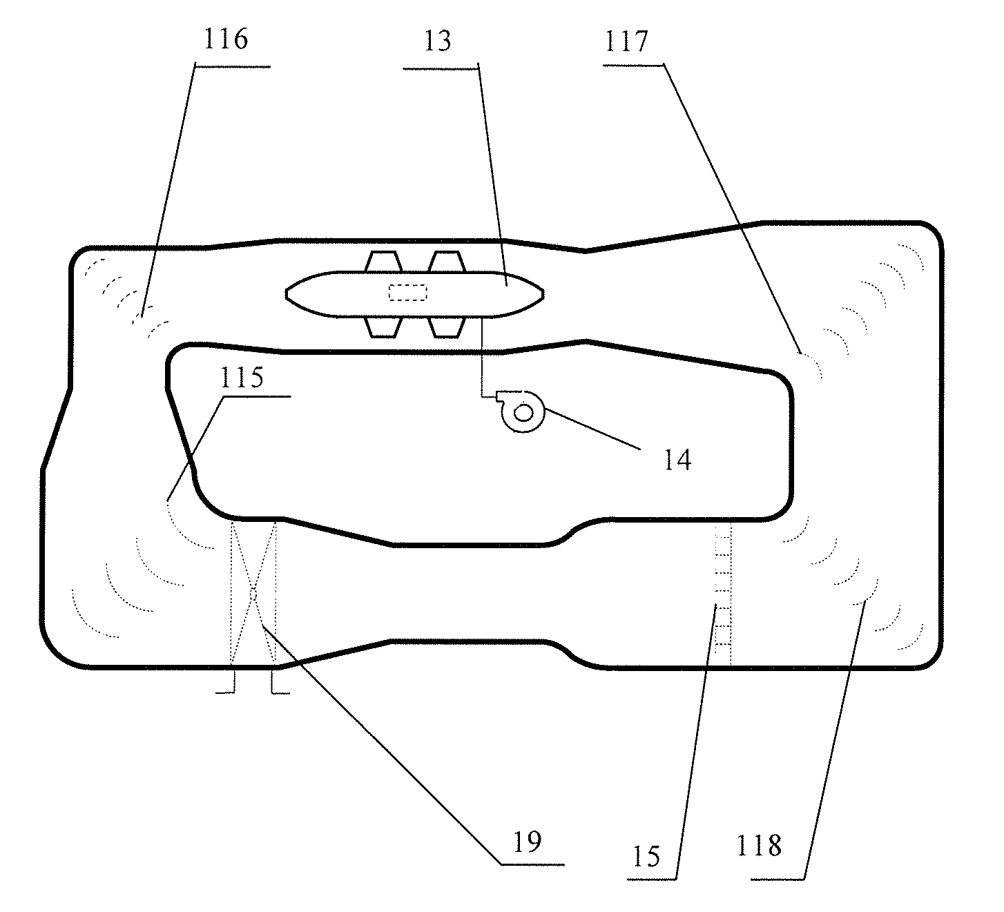
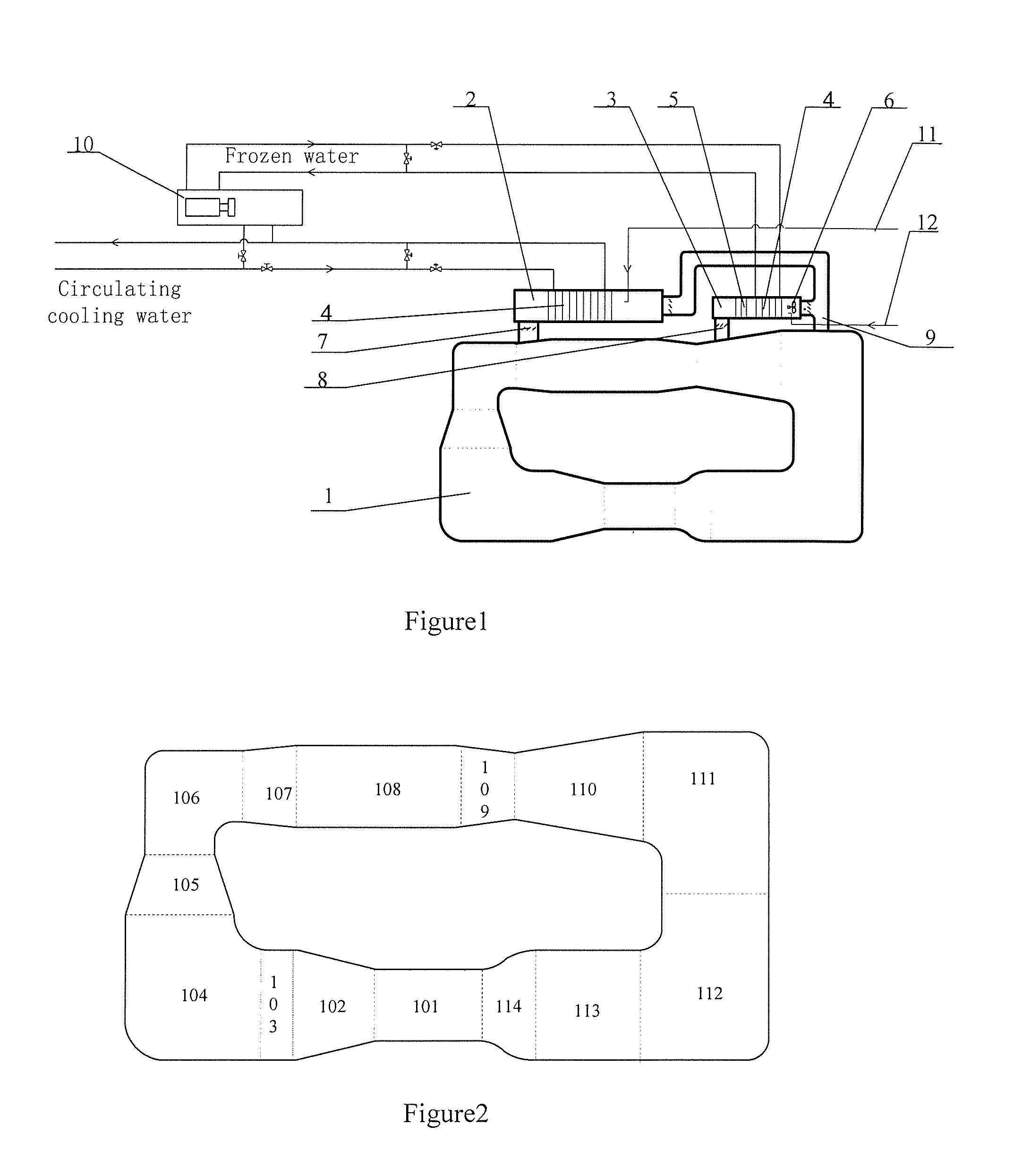
[0097]The sand and dust blowing environmental testing equipment generally comprises a circulating air duct, a compressed air source, a sand and dust material system, a temperature control system, a humidity control system and an air duct pressure control system, wherein the circulating air duct is used to provide the place for the test piece in the sand and dust blowing environment; the compressed air source and the sand and dust material system (not shown in the figures) are used to realize the concentration of the experiment environment; the temperature control system, humidity control system and the air duct pressure control system form the air-conditioning system and connect with each other through the circulating air duct and pipes, which are configured with several valves for effectively adjusting the flow quantity of the sand and dus...


PUM


Abstract

A temperature adjusting device is included with a sand and dust environmental testing system. The sand and dust environmental testing system includes: a circulating air duct, including a contraction section, a test section and a separation section etc.; a main blower; U-type separators and guide vanes, respectively configured at four corners of the circulating air duct. The temperature adjusting device includes: heat exchange pipes distributed in the U-type separators; four groups of guide vanes. Three groups of the guide vanes are configured with heat exchange medium holes and the other group of the guide vanes is equipped with heating device. An electric heater is accommodated in the second contraction section. An intelligent temperature control includes: building a neural network system structure; blended learning training of neural network parameters; PI control; and amplitude limitation processing.

Description

BACKGROUND OF THE INVENTION[0001]1. Technical Field[0002]The present invention relates to a temperature-adjusting device and an intelligent temperature control method for the sand and dust environmental testing systems and belongs to the technical field of sand and dust environmental testing.[0003]2. Description of Related Art[0004]Sand and dust environment is an important environmental factor which has caused the malfunction of many engineering and military hardware, wherein main damage types are erosion, abrasion, corrosion and infiltration etc. The sand and dust blowing test is an important method for inspecting the environmental adaptability and reliability of the vehicles, aircraft, electric and military equipment in the desert & arid areas and under the windy & dusty weather conditions.[0005]The existing sand and dust environmental testing system adopts two air-conditioning boxes, a big one and a small one, to control the temperature, as shown in FIG. 1. The Chinese Invention ...

Claims


Application Information

Patent Timeline
Patent Type & Authority Applications(United States)
IPC IPC(8): G05D23/19
CPCG01M99/002G01M9/04
Inventor WANG, JUNZHANG, HUALI, YUNZEMING, ZHANGPENGZHU, KEYONGMA, ZHIHONGZHANG, LIZHENZHAO, CHEN
Owner BEIHANG UNIV
Why Eureka
Try Eureka