Low aspect ratio spiral-bound vrla battery

Active Publication Date: 2012-03-01
HIGHWATER INNOVATIONS
View PDF9 Cites 6 Cited by
  • Summary
  • Abstract
  • Description
  • Claims
  • Application Information

AI Technical Summary

Benefits of technology

[0012]An advantage of the foregoing VRLA cell and battery is that stacking the cells may be possible by the nature of the low aspect ratio (L<D) of the cells. Accordingly, multiple cells may be interconnected with less space than with conventional spiral wound VRLA cells.
[0013]A secondary advantage of the spiral-wound cell having a low aspect ratio, i.e., L<D, is that cells having shorter grids in the L direction and thus may exhibit improved cell performance due to lower electrical resistance from one end of the cell to the opposite end of the cell. Also, by having the diameter greater than the length of the cells, mor

Problems solved by technology

One disadvantage of conventional spiral-wound VRLA batteries made of multiple VRLA cells is the space requirements for obtaining batteries with the desired voltage.
Despite the fact that these batteries may be constructed in a custom six-cavity container shape with cast-on-terminal inter-cell connections, these batteries are not typically compact and may not readily interconnected with one another for high voltage HEV applications.
Electrical terminals for the VRLA batteries tend to protrude from the top of the cells thereby further limiting the ability to stack the high aspect ratio cells.
High aspect ratio batteries also have tall grids i

Method used


Image

  • Low aspect ratio spiral-bound vrla battery
  • Low aspect ratio spiral-bound vrla battery
  • Low aspect ratio spiral-bound vrla battery

Examples


example 1

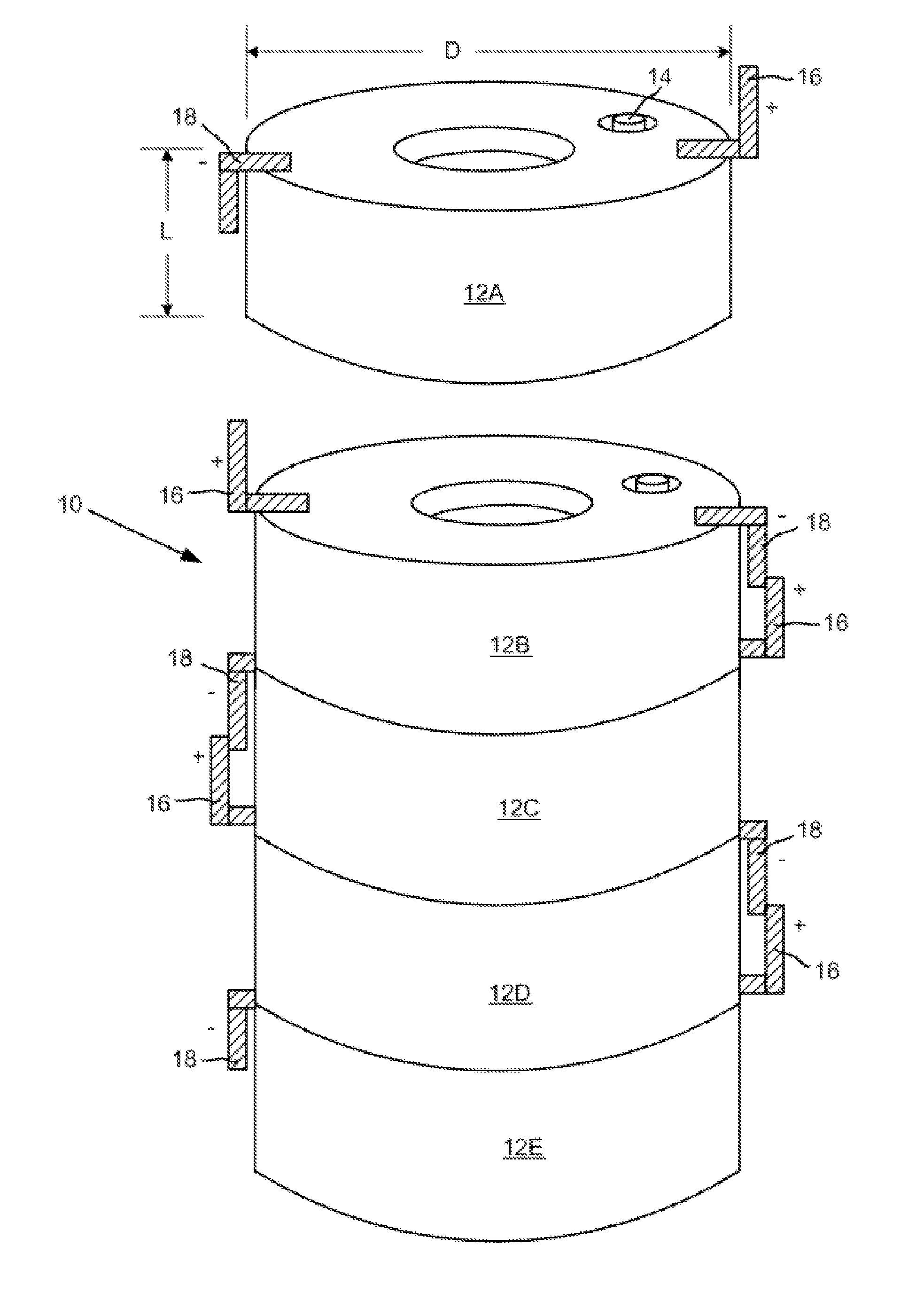
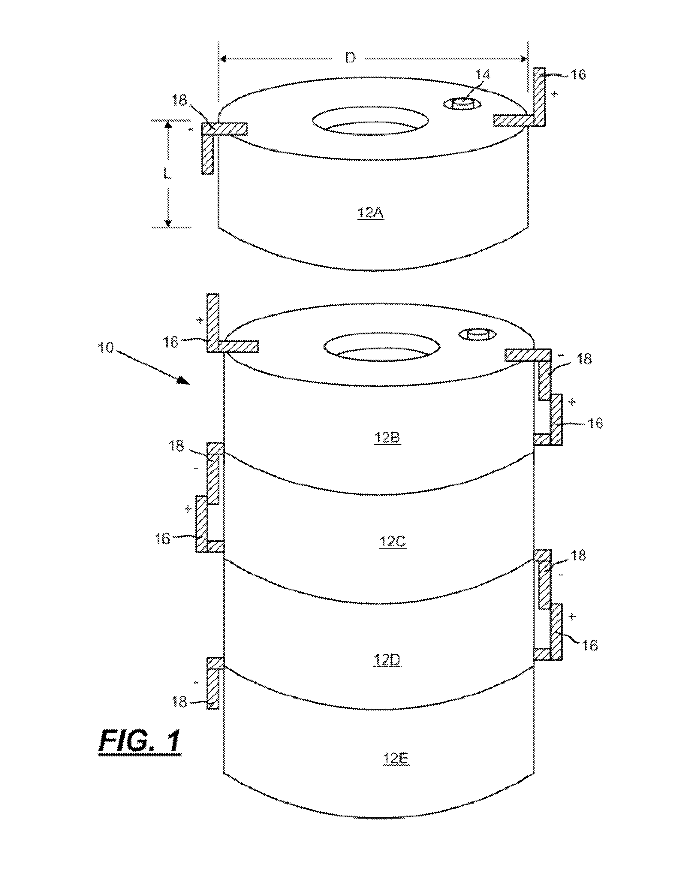
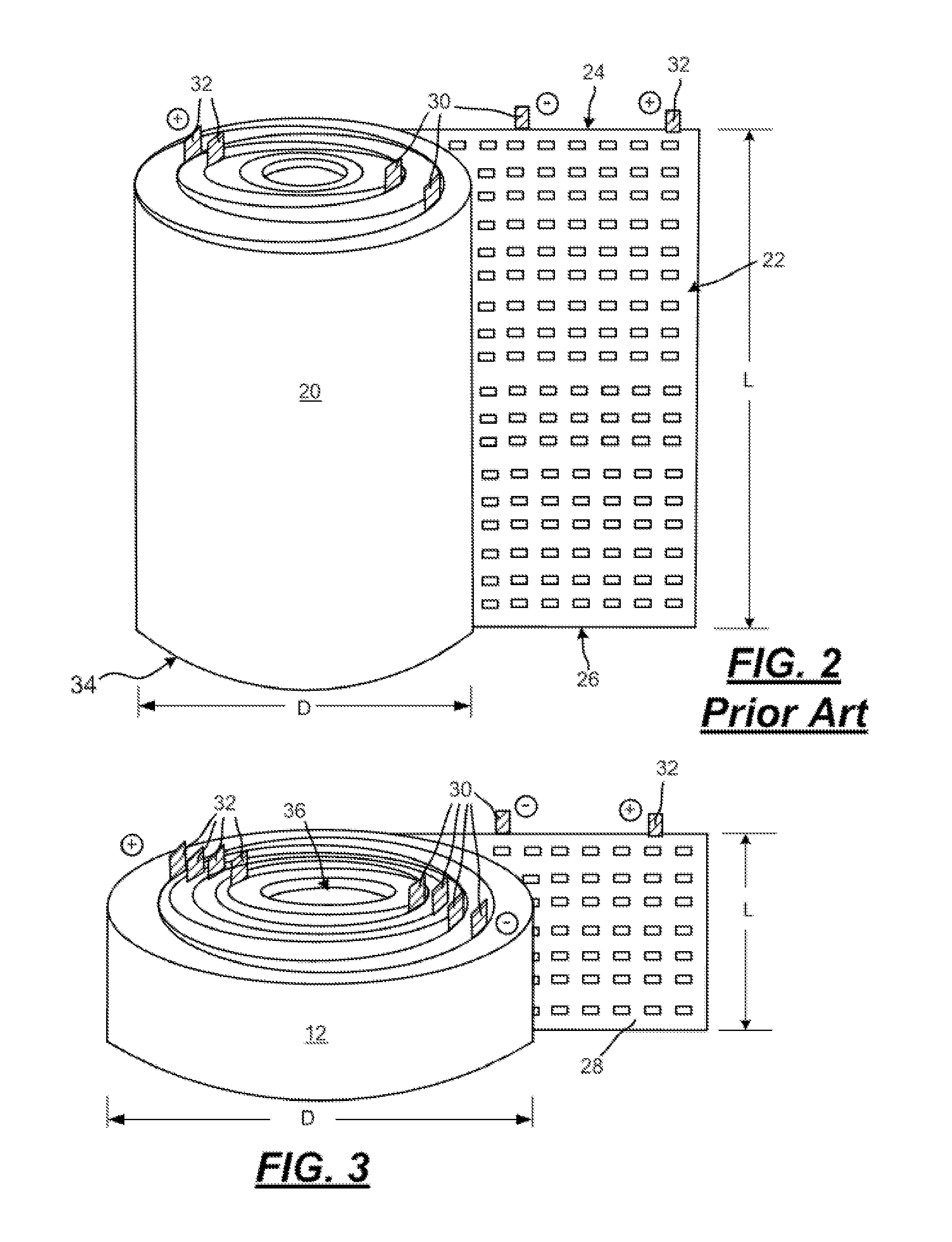
[0042]A low aspect ratio spiral-wound VRLA battery is constructed by first preparing positive grids cast from a conventional lead-tin-calcium alloy and negative grid plates cast from a lead-calcium alloy. In this example both grid plates have a width of 2.54 cm and a length of 100 cm thus having a geometric area of approximately 254 cm2 per side. The positive grid has a thickness of 1.2 mm while the negative grid is 1.0 mm thick. The positive plate is pasted to a thickness of 1.4 mm using a conventional litharge based oxide containing 24 wt. % red lead. The negative grid is pasted with a conventional leady oxide paste to a thickness of 1.2 mm using a paste mix that includes a conventional negative expander mixture and state of the art graphite (2 wt. %) and activated carbon (2 wt. %) additives for improved high rate partial state of charge cycling. Immediately after pasting the positive and negative “plates,” the plates are wound around a 4 mm mandrel while interleaving the plates w...

example 2

[0044]A low aspect ratio spiral-wound VRLA battery with a central core for cooling is constructed by first preparing both positive and negative grids cast from a lead-tin-calcium alloy. In this example both grids have a width of 2.54 cm and a length of 153 cm thus having a geometric area of approximately 390 cm2 per side. The positive grid has a thickness of 1.2 mm while the negative grid is 1.0 mm thick. The positive plate is pasted to a thickness of 1.4 mm using a conventional litharge based oxide containing 24 wt. % red lead. The negative grid is pasted to a thickness of 1.2 mm using a conventional leady oxide / expander paste mix without the graphite and activated carbon additives used in Example 1. Immediately after pasting the positive and negative “plates,” the plates are wound around a 25.4 mm mandrel while interleaving the plates with an absorbent glass matte battery separator (1.3 mm thick) and a sheet (0.5 cm×153 cm) of carbon paper (0.005 mm thick). The finished low aspect...


PUM


Abstract

A valve regulated lead-acid (VRLA) battery having a plurality of stacked, interconnected spiral-wound cells. Each cell has a length (L) less than a diameter (D) and each cell has a non-conductive case containing spiral-wound positive and negative plates, a separator between the plates, an acidic electrolyte, and a positive post and a negative post disposed through the case for electrical connection to an adjacent cell in series.

Description

TECHNICAL FIELD[0001]The disclosure relates to automotive batteries and in particular to valve-regulated lead-acid (VRLA) batteries and to construction techniques for improving cell and battery performance.BACKGROUND AND SUMMARY[0002]The automotive industry is in need of a battery technology that affords high voltage, high power, low cost, long life and recyclability for a growing number applications such as in hybrid electrical vehicles (HEV). Valve-regulated lead-acid (VRLA) battery technology may meet or exceed many of the requirements for low cost, sufficient power, and recyclability and very recently has been demonstrated to meet the life requirements in terms of high rate partial state of charge cycling. Despite these positive attributes, improvements in VRLA technology may be required to improve energy density, form, function, fitment and thermal management, particularly for use in hybrid electric vehicles.[0003]One type of VRLA battery technology that may be used is spiral-w...

Claims


Application Information

Patent Timeline
IPC IPC(8): H01M10/36H01M50/213H01M50/51H01M50/522H01M50/541
CPCH01M10/121H01M10/06H01M10/5004H01M10/5016H01M10/503H01M10/5061Y02E60/126Y02T10/7016H01M2/0245H01M10/0587H01M10/0431H01M2/28H01M2/204H01M2/202H01M2/1077H01M10/125H01M10/625H01M10/643H01M10/613H01M10/656Y02E60/10Y02P70/50H01M50/51H01M50/522H01M50/541H01M50/213H01M6/00Y02T10/70H01M50/258
Inventor BRILMYER, GEORGE H.
Owner HIGHWATER INNOVATIONS
Why Eureka
Try Eureka