Cone-aware spare cell placement using hypergraph connectivity analysis

a hypergraph and connectivity analysis technology, applied in the field of spare cell placement, can solve the problems of large number of cells, difficult physical design without the aid of computers, and complicated connections between cells

Active Publication Date: 2012-03-01
GLOBALFOUNDRIES US INC
View PDF5 Cites 15 Cited by
  • Summary
  • Abstract
  • Description
  • Claims
  • Application Information

AI Technical Summary

Benefits of technology

[0012]It is therefore one object of the present invention to provide an improved method of placing spare cell locations in an integrated circuit design.
[0013]It is another object of the present invention to provide such a method which more accurately places spare cell locations proximate critical logic.
[0014]It is yet another object of the present invention to provide such a method which more efficiently places spare cell locations by maximizing the efficacy of spare cell placement which in turn minimizes the number of spare cells needed.

Problems solved by technology

An IC may include a very large number of cells and require complicated connections between the cells.
Due to the large number of components and the details required by the fabrication process for very large scale integrated (VLSI) devices such as microprocessors and application-specific integrated circuits (ASICs), physical design is not practical without the aid of computers.
Because the circuit design is substantially complete (i.e., it conforms to various design requirements such as timing and slew), it is important to minimize the impact of any changes which might otherwise lead to violations and thus require additional iterations of the design steps, meaning significant computational expense.
The use of spare cells greatly simplifies implementation of ECOs but there can still be problems with the locations of these cells.
Since the filler percentage is applied globally to an entire design, some areas of the circuit which are more stable can end up getting too many filler cells, while other areas do not get enough.
Furthermore, typical placement tools can push filler cells away from the most critical logic (which is often unstable), so even though there are filler cells available, they are not located close enough to be of use.
Placement tools that partition the logic into separate bins can experience additional stability issues whenever the bin sizes or locations change.
However, this spreading force is not effective for ECO work because it adds only a small amount of space to a large region instead of targeting areas that have a higher potential to change.
These problems are exacerbated in high density circuit designs which have gone through multiple ECOs.
The interior filler cells are exhausted early on, leaving an insufficient number of spare cell locations that are still close enough to associated logic gates.

Method used


Image

  • Cone-aware spare cell placement using hypergraph connectivity analysis
  • Cone-aware spare cell placement using hypergraph connectivity analysis
  • Cone-aware spare cell placement using hypergraph connectivity analysis

Examples


Embodiment Construction

)

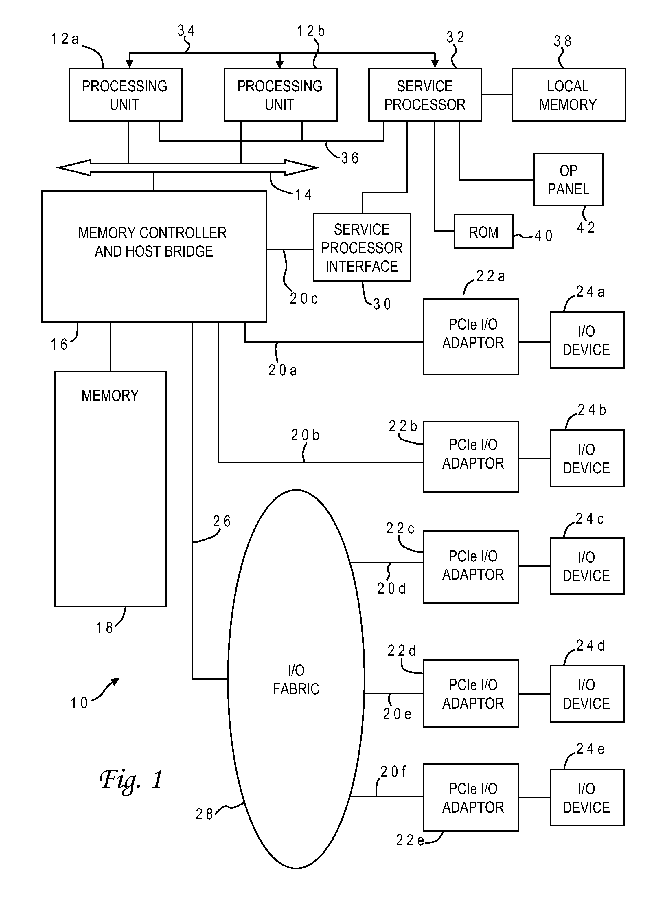
[0027]With reference now to the figures, and in particular with reference to FIG. 1, there is depicted one embodiment 10 of a computer system in which the present invention may be implemented to carry out the design of an integrated circuit. Computer system 10 is a symmetric multiprocessor (SMP) system having a plurality of processors 12a, 12b connected to a system bus 14. System bus 14 is further connected to a combined memory controller / host bridge (MC / HB) 16 which provides an interface to system memory 18. System memory 18 may be a local memory device or alternatively may include a plurality of distributed memory devices, preferably dynamic random-access memory (DRAM). There may be additional structures in the memory hierarchy which are not depicted, such as on-board (L1) and second-level (L2) or third-level (L3) caches.

[0028]MC / HB 16 also has an interface to peripheral component interconnect (PCI) Express links 20a, 20b, 20c. Each PCI Express (PCIe) link 20a, 20b is connected t...


PUM


Abstract

Spare cells are placed in an IC design by assigning different spare utilization rates to logic cones, applying the rates to corresponding spare cell regions surrounding cells in the cones, identifying any overlap of regions from different logic cones, and inserting a spare cell at the overlapping region having the highest spare utilization rate. The best location for the spare cell is computed using a hypergraph wherein the cells are edges and the regions are nodes. Any node that is dominated by another node is removed and its edge is extended to the dominating node. The spare cell is inserted in the region having the most edges (the edges can be weighted). The process is repeated iteratively, updating the hypergraph by removing nodes connected to spare cell location, and inserting the next spare cell at a region corresponding to the node which then has the greatest number of connected edges.

Description

BACKGROUND OF THE INVENTION[0001]1. Field of the Invention[0002]The present invention generally relates to the design of semiconductor chips and integrated circuits, and more particularly to a method of inserting spare cell locations in an integrated circuit design to accommodate engineering changes.[0003]2. Description of the Related Art[0004]Integrated circuits are used for a wide variety of electronic applications, from simple devices such as wristwatches, to the most complex computer systems. A microelectronic integrated circuit (IC) chip can be thought of as a collection of logic cells with electrical interconnections between the cells, formed on a semiconductor substrate (e.g., silicon). An IC may include a very large number of cells and require complicated connections between the cells. A cell is a group of one or more circuit elements such as transistors, capacitors, resistors, inductors, and other basic circuit elements combined to perform a logic function. Cell types inclu...

Claims


Application Information

Patent Timeline
Patent Type & Authority Applications(United States)
IPC IPC(8): G06F17/50
CPCG06F17/5072G06F2217/72G06F2217/02G06F30/392G06F2111/20G06F2117/06
Inventor GOODMAN, BENJIMAN L.HIETER, NATHANIEL D.HOPKINS, JEREMY T.WARD, SAMUEL I.
Owner GLOBALFOUNDRIES US INC
Why Eureka
Try Eureka