Cannula Systems and Methods

a technology of cannulas and cannulas, applied in the field of cannula systems and methods, can solve the problems of insufficient blood flow, impaired cardiac function, congestive heart failure, etc., and achieve the effect of eliminating the need for suturing and preventing blood leakag

Active Publication Date: 2012-03-08
SPENCE PAUL A
View PDF4 Cites 84 Cited by
  • Summary
  • Abstract
  • Description
  • Claims
  • Application Information

AI Technical Summary

Benefits of technology

[0010]This disclosure describes new devices, methods and systems for directing the flow of material from a chamber of an organ, e.g., the left atrium of a heart via a wall of the organ. In one embodiment, the flow of material is directed without the need to place a cannula into the chamber, e.g., the cannula system comprises a retention member that provides a smooth inflow for blood (eliminating clots) into an elongate tubular member, avoids suction against the atrial wall, and is held in place with a retaining means that provides solid fixation to prevent blood leaks and cannula dislodgement and eliminates the need for suturing.

Problems solved by technology

Congestive heart failure occurs when cardiac function is impaired to the point that there is insufficient blood flow to support a person's activities.
Unfortunately, cardiac transplantation is limited by the donor pool and each year fewer than 2,000 patients undergo this procedure.
Embolization of material can cause damage to any part of the body but embolization to the brain is the most feared complication.
Entry of clot into the brain generally causes brain dysfunction and the results can be mild—such as a temporary and slight slurring of speech or gait impairment to a terrible catastrophic loss of function that leaves a patient in a wheelchair or bedridden and unable to communicate.
In this situation death may be a potential outcome.
Another deficiency that is encountered with cannulation of the left atrium is collapse of the left atrium and occlusion (temporary or permanent) of the inflow cannula by atrial tissue.
A cannula tip sitting in the left atrium and flowing at 2 to 3 liters per minute can easily suction a part of the atrial wall into the cannula leading to cannula obstruction and loss of pump flow.
Alternatively, the cannula may completely clot off and make it impossible to pump blood when the obstruction is relieved.
The atrial tissue may also be injured.
Another problem with a cannula implanted in the left atrium is that it must be fastened securely in position.
If fat is pushed into the heart, it can embolize anywhere in the circulation.
Furthermore, creating a defect in the wall of the atrium to introduce a cannula is also a difficult problem.
Simply pushing a cannula through a small hole is dangerous since the atrial tissue may tear.
This may leave a large hole which is difficult to close.
It also creates further problems because a cannula may “snag” inside the delivery catheter.
To guarantee delivery, there are serious development and manufacturing problems in maintaining the correct gap tolerances between the cannula and the catheter.
And even with excellent design, the operator may be forced to insert a cannula along a circuitous course.
Bends may make it impossible for even the best engineered system to permit delivery of the cannula.

Method used


Image

  • Cannula Systems and Methods
  • Cannula Systems and Methods
  • Cannula Systems and Methods

Examples


Embodiment Construction

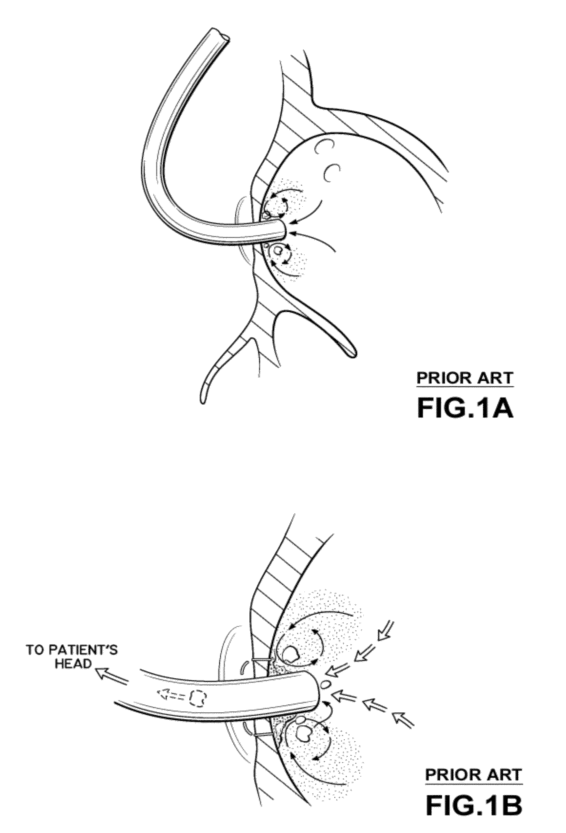
[0057]FIG. 1A illustrates an inflow cannula for a heart pump positioned in the left atrium of the heart according to a known approach, with the tip of the inflow cannula extending about one centimeter into the left atrium from the atrial septum. While blood flow into the inflow cannula is brisk, the blood around the inflow cannula is stagnant and can form eddy currents that limit the entry of fresh blood to wash the area surrounding the inflow cannula. Clots may form in this region.

[0058]FIG. 1B shows that a clot has formed and attached to the atrial wall around the inflow cannula. Other clots may form along the side of the inflow cannula, and may not attach securely to the inflow cannula and thus may become dislodged. Clots may be drawn into the inflow cannula by the strong flow induced by the blood pump.

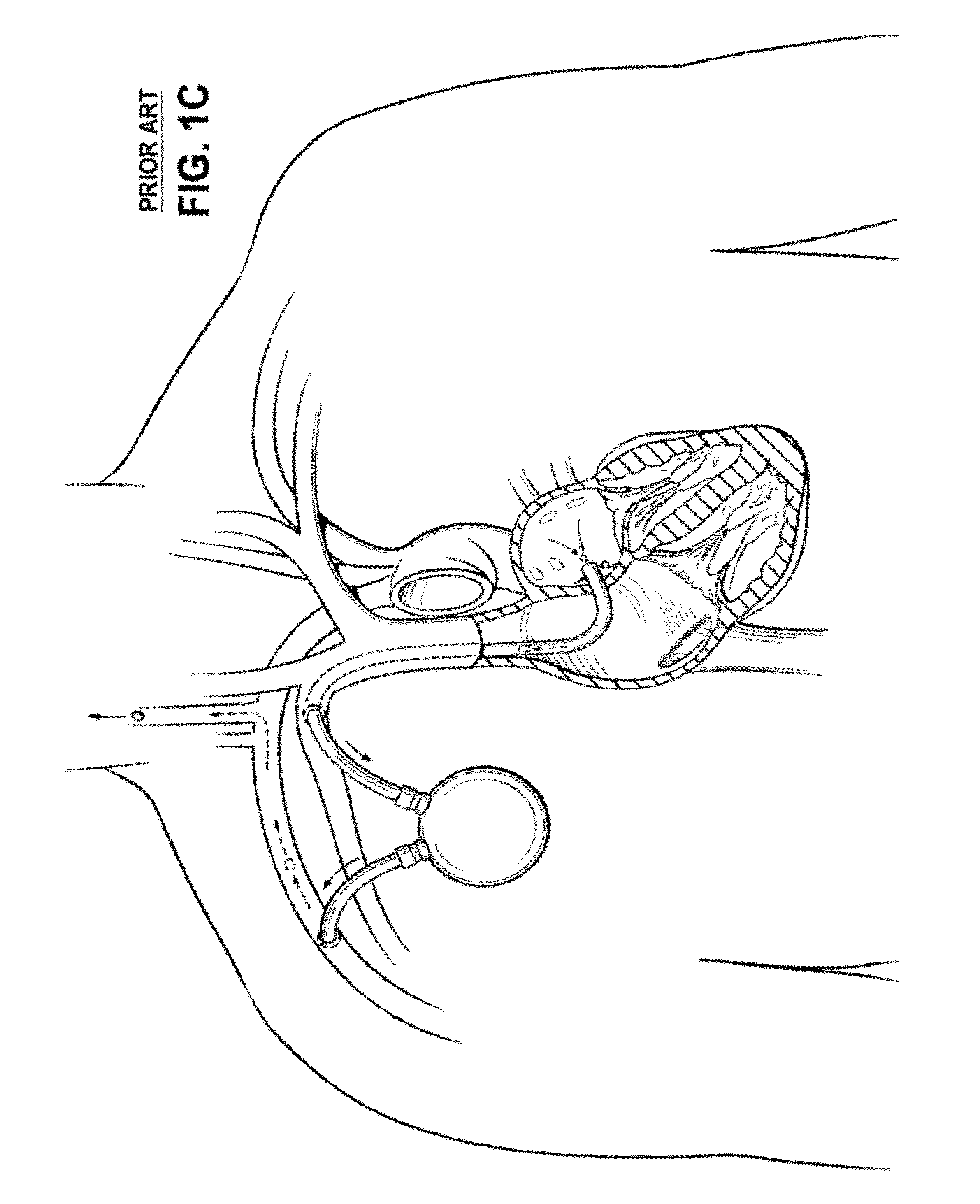
[0059]FIG. 1C indicates a catastrophic outcome for a clot originating around the inflow cannula inside the left atrium. A clot has formed around the inflow cannula tip, entered the...


PUM


Abstract

Disclosed herein is a cannula assembly for directing the flow of material from an organ chamber, e.g., blood from the left chamber of the heart, and methods of placing the cannula assembly in fluidic communication with the chamber. The cannula assembly includes an elongate tubular member and a coupling assembly disposed at the distal end of elongate tubular member. The elongate tubular member includes a lumen extending from a distal opening at the distal end to a proximal opening at the proximal end. The coupling assembly includes a retaining element and a retention member configured to cooperate with each other and with the portion of the organ wall surrounding the opening in the wall to couple or anchor cannula system to the wall and to provide fluidic communication between the distal opening of the elongate tubular member and the organ chamber.

Description

CROSS-REFERENCE TO RELATED APPLICATIONS[0001]This application claims the benefit of U.S. Provisional Application No. 61 / 459,055, filed Dec. 6, 2010, and U.S. Provisional Application No. 61 / 402,892, filed Sep. 7, 2010, the entire contents of which applications are hereby incorporated by reference.FIELD OF INVENTION[0002]Described herein is a cannula system to direct the flow of material from the chamber of an organ, e.g., the left atrium of a heart, and methods of placing the cannula system in fluidic communication with the organ chamber.BACKGROUND OF THE INVENTION[0003]Congestive heart failure occurs when cardiac function is impaired to the point that there is insufficient blood flow to support a person's activities. It is the largest problem in cardiac care today and there are more than 5 million patients with this diagnosis in the U.S. In general, patients can be treated with medications, but when symptoms are advanced, cardiac transplantation or the implantation of blood pumps ma...

Claims


Application Information

Patent Timeline
Patent Type & Authority Applications(United States)
IPC IPC(8): A61M1/10
CPCA61B2017/1135A61M1/3653A61M1/3656A61M1/3659A61M60/20A61M60/861A61M60/88A61M60/873A61M60/857
Inventor SPENCE, PAUL A.
Owner SPENCE PAUL A
Why Eureka
Try Eureka