Surface acoustic wave device, electronic apparatus, and sensor apparatus

a surface acoustic wave and electronic equipment technology, applied in the direction of device material selection, oscillation generators, generators/motors, etc., can solve the problems of unsatisfactory reflection efficiency of the saw by the reflector, damage to product reliability and quality, and difficulty in realizing the reduction in size and a high q valu

Inactive Publication Date: 2012-03-15
SEIKO EPSON CORP
View PDF3 Cites 29 Cited by
  • Summary
  • Abstract
  • Description
  • Claims
  • Application Information

AI Technical Summary

Benefits of technology

[0026]In the SAW resonator of this embodiment, the depth G of the inter-electrode-finger grooves may satisfy the relationship 0.01λ≦G≦0.0695λ. If the depth G of the inter-electrode-finger grooves is set within this range, it is possible to suppress a frequency fluctuation in an operation temperature range (for example, −40° C. to +85° C.) to be small, and even when a manufacturing variation occurs in the depth of the inter-electrode-finger grooves, it is possible to suppress the shift amount of a resonance frequency between individual SAW resonators within a correctable range.
[0090]The SAW device may further include an oscillation circuit which drives the IDT. Therefore, it is possible to obtain a SAW oscillator having a very small frequency fluctuation in a wide operation temperature range, a low CI value, and excellent oscillation stability.

Problems solved by technology

Thus, the reflection efficiency of the SAW by the reflector is unsatisfactory compared to an ST cut quartz crystal SAW device in which a SAW propagates along the substrate surface, making it difficult to realize reduction in size and a high Q value.
As a result, if a variation occurs in the frequency fluctuation with a change in the temperature of the SAW device, product reliability and quality are damaged.
When the frequency-temperature characteristic of the SAW device is a quadratic curve in the operation temperature range, it is difficult to realize minimization of a frequency fluctuation range or an inflection point.
If the electrode thickness of the IDT simply increases, there is a problem in that deterioration in frequency stability (depending on a change in the line occupancy) or the like occurs due to stress migration at the time of electrical conduction or side etching at the time of IDT formation.
However, in all the SAW devices, excluding the SAW device described in JP-B-1-34411 which excites a leaky SAW, since the frequency-temperature characteristic in the operation temperature range is expressed by a quadratic curve, it is difficult to sufficiently reduce a frequency fluctuation range or to realize an inflection point.
For this reason, it may be impossible to sufficiently cope with recent requirements for a SAW device, such as expansion or high-precision performance of an operation temperature range, long-term operation stability in an environment in which temperature undergoes severe changes, and the like.
In the SAW resonator of this embodiment, it is not possible to realize an excellent frequency-temperature characteristic and a high Q value simultaneously, and it is difficult to use the SAW resonator as an oscillator.

Method used


Image

  • Surface acoustic wave device, electronic apparatus, and sensor apparatus
  • Surface acoustic wave device, electronic apparatus, and sensor apparatus
  • Surface acoustic wave device, electronic apparatus, and sensor apparatus

Examples


example 1

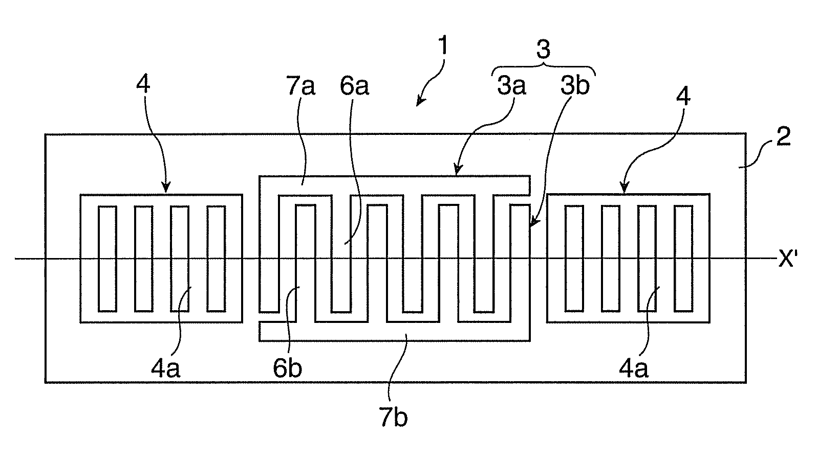
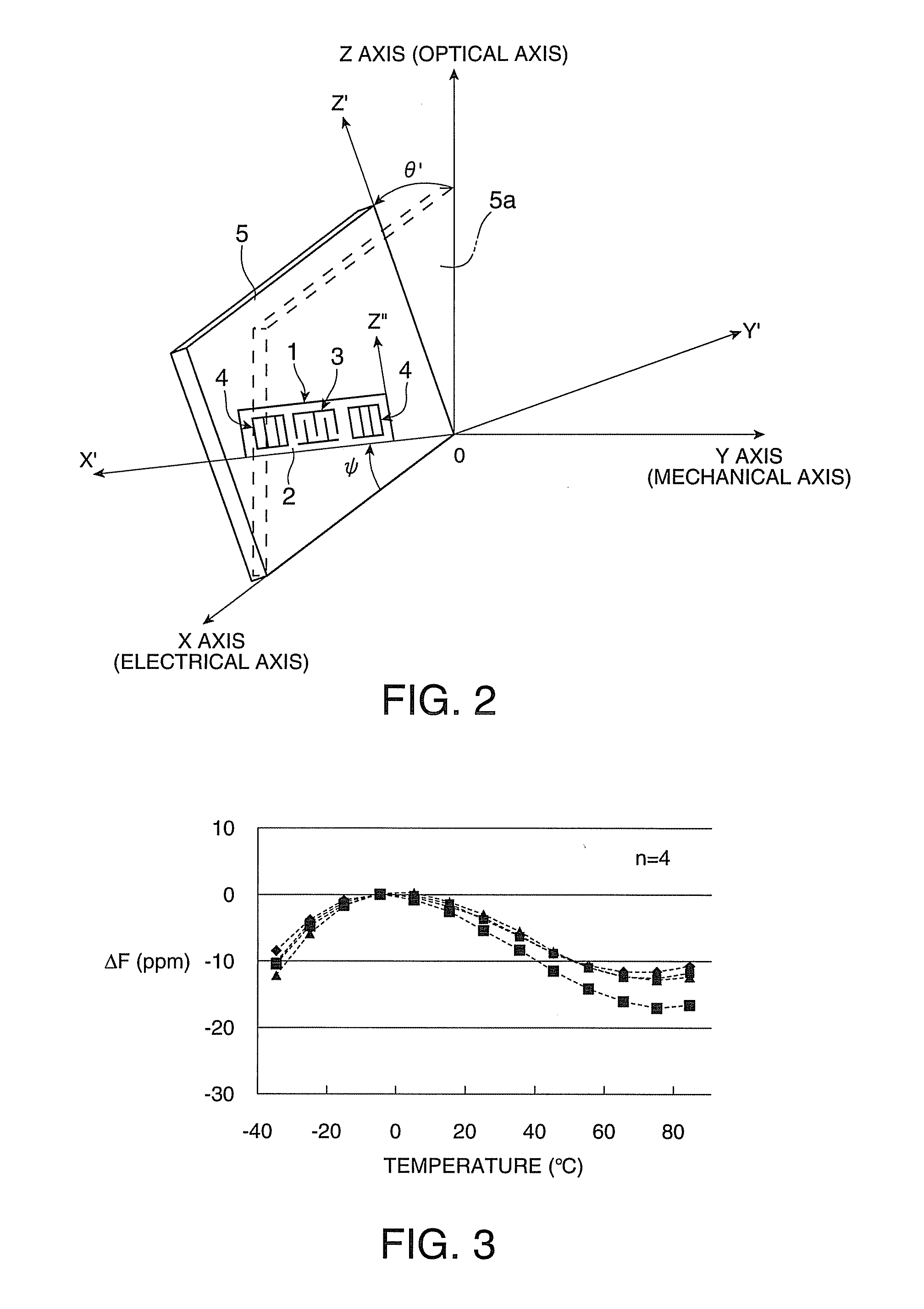
[0117]The specification of the SAW resonator 11 was as follows.[0118]Quartz crystal substrate size: 5.0×1.5 (mm)[0119]Euler angles: (0°, 123°, ψ)[0120]Number of pairs of IDT: 180[0121]Number of reflectors (per side): 78

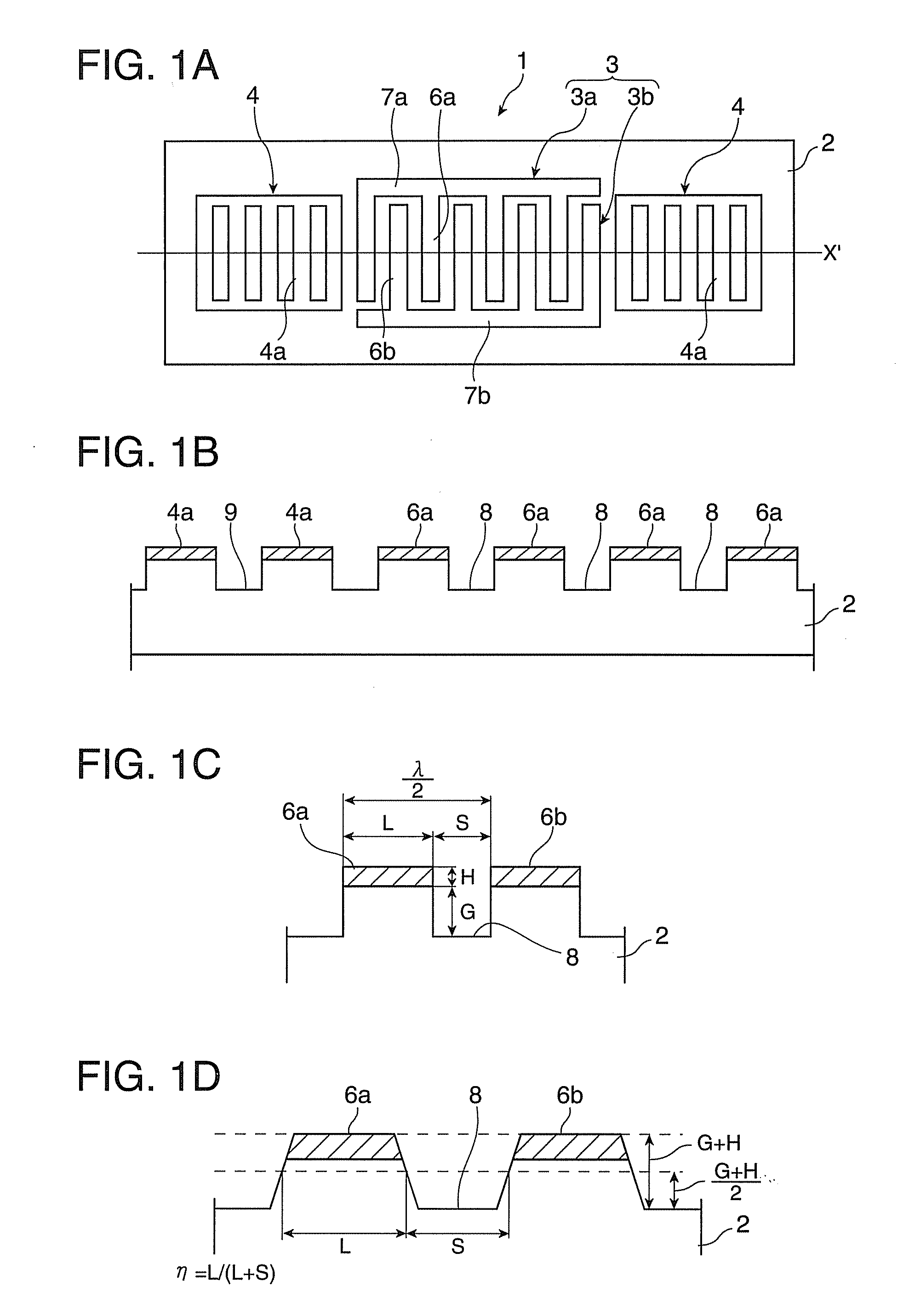
[0122]The IDT 13 was designed as follows.[0123]SAW wavelength λ: 7.9 (μm)[0124]Electrode material: Al[0125]Electrode finger thickness H: 0.02λ (2%λ)=0.1580 (μm)[0126]Electrode finger pitch Pt: λ / 2=3.95 (μm)[0127]Electrode finger line width Lt: 0.625Pt=2.4688 (μm)[0128](line occupancy η: 0.625)

[0129]The reflectors 14 were designed as follows.[0130]Electrode material: Al[0131]Conductor strip thickness H: 2%λ (0.02λ)=0.1580 (μm)[0132]Conductor strip pitch Pr: λ / 2=3.95 (μm)[0133]Conductor strip line width: 0.725Pr=2.8638 (μm)[0134](line occupancy ηr: 0.725)

[0135]The inter-electrode-finger grooves 17 were designed as follows.[0136]Depth: 0.045λ (4.5%λ)=0.3555 (μm)[0137]Effective electrode finger thickness: 0.065λ (6.5%λ)=0.5135 (μm)

[0138]With regard to the SAW resonator 11...


PUM


Abstract

A SAW device 11 has an IDT which is provided on the principal surface of a quartz crystal substrate 12 having Euler angles (−1.5°≦φ≦1.5°, 117°≦θ≦142°, 42.79°≦|ψ|≦49.47°) and excites a SAW in a stopband upper end mode, and a pair of reflectors which are arranged on both sides of the IDT. Inter-electrode-finger grooves are recessed between the electrode fingers of the IDT, and inter-conductor-strip grooves are recessed between the conductor strips of the reflectors. The wavelength λ of the SAW and the depth G of the inter-electrode-finger grooves satisfy 0.01λ≦G. An IDT line occupancy η and the depth G of the inter-electrode-finger grooves satisfy a predetermined relational expression. The IDT line occupancy η and a reflector line occupancy ηr satisfy the relationship η<ηr. Therefore, an excellent frequency-temperature characteristic and a high Q value in an operation temperature range are realized simultaneously.

Description

TECHNICAL FIELD [0001]The present invention relates to a surface acoustic wave device, such as a resonator or an oscillator using a surface acoustic wave (SAW), and an electronic apparatus and a sensor apparatus including the same.RELATED ART [0002]SAW devices are widely used in electronic apparatuses, such as a mobile phone, a hard disk, a personal computer, a receiver tuner of BS and CS broadcasts, an apparatus which processes a high-frequency signal or an optical signal propagating through a coaxial cable or an optical cable, a server network apparatus which requires a high-frequency and high-precision clock (low jitter and low phase noise) in a wide temperature range, and a wireless communication apparatus, or various sensor apparatuses, such as a pressure sensor, an acceleration sensor, and a rotational speed sensor. In these apparatuses and devices, in particular, with the realization of a high-frequency reference clock due to recent high-speed performance of information commu...

Claims


Application Information

Patent Timeline
Patent Type & Authority Applications(United States)
IPC IPC(8): H01L41/047H03B5/32H01L41/09H01L41/18H01L41/22H01L41/311H03B5/30H03H9/145H03H9/25
CPCH03H9/02551H03H9/14594H03H9/02834H03H9/02661
Inventor YAMANAKA, KUNIHITO
Owner SEIKO EPSON CORP
Why Eureka
Try Eureka