Nitrogen rejection and liquifier system for liquified natural gas production

a liquifier and natural gas technology, applied in refrigeration, liquifaction, solidification, etc., can solve the problems of high energy requirements for purifying renewable methane, high capital and operating costs, and high cleanup costs of biogas/landfill gas, etc., to maximize liquefied natural gas production and minimize product flash losses

Inactive Publication Date: 2012-03-22
LINDE AG
View PDF8 Cites 15 Cited by
  • Summary
  • Abstract
  • Description
  • Claims
  • Application Information

AI Technical Summary

Benefits of technology

[0013]The end flash from the flash vessel has an additional advantage in that the liquid outlet of a flash is at equilibrium which implies that it will produce some more gas inside the line between the end flash and storage tank because of product line pressure drop. Therefore, it is best practice that the flash pressure be lower than the storage pressure. To maximize liquefied natural gas production and minimize product flash losses, the first flash within the flash vessel is effected at a pressure lower than the storage tank pressure, whence, the liquid coming down from the end-flash tank will be sub-cooled at storage pressure. A cryogenic pump can be utilized to overcome this concern, but involves additional cost, maintenance and potential reliability issues. Therefore it is advisable to have horizontal storage tanks, and a cold box layout so that the liquid level inside the end flash will be higher by a few hundreds of mbar of equivalent liquefied natural gas head that the top of the storage and to use that additional head to pressurize FIG. 2c.

Problems solved by technology

Further, the energy that is required to purify the renewable methane is significant.
The cleanup of biogas / landfill gas is both capital and power intensive because it contains a large number of trace and bulk contaminants in fairly large concentrations.
However, these processes can be expensive in both capital and operating costs and it is important to minimize these costs to achieve an economically viable process.
LNG production is particularly challenging since all condensable contaminants including carbon dioxide must be removed to low ppm levels.

Method used


Image

  • Nitrogen rejection and liquifier system for liquified natural gas production
  • Nitrogen rejection and liquifier system for liquified natural gas production
  • Nitrogen rejection and liquifier system for liquified natural gas production

Examples


Embodiment Construction

[0022]Landfill gas is purified and all the water, sulfur compounds, NMOCs and carbon dioxide are removed in a pre-purification process. The purified gas contains methane, nitrogen and oxygen and has the following composition:

TABLE 1NRU Feed Gas CompositionSpeciesMole FractionCarbon Dioxide0.0100Nitrogen0.2160Methane0.7720Oxygen0.0020

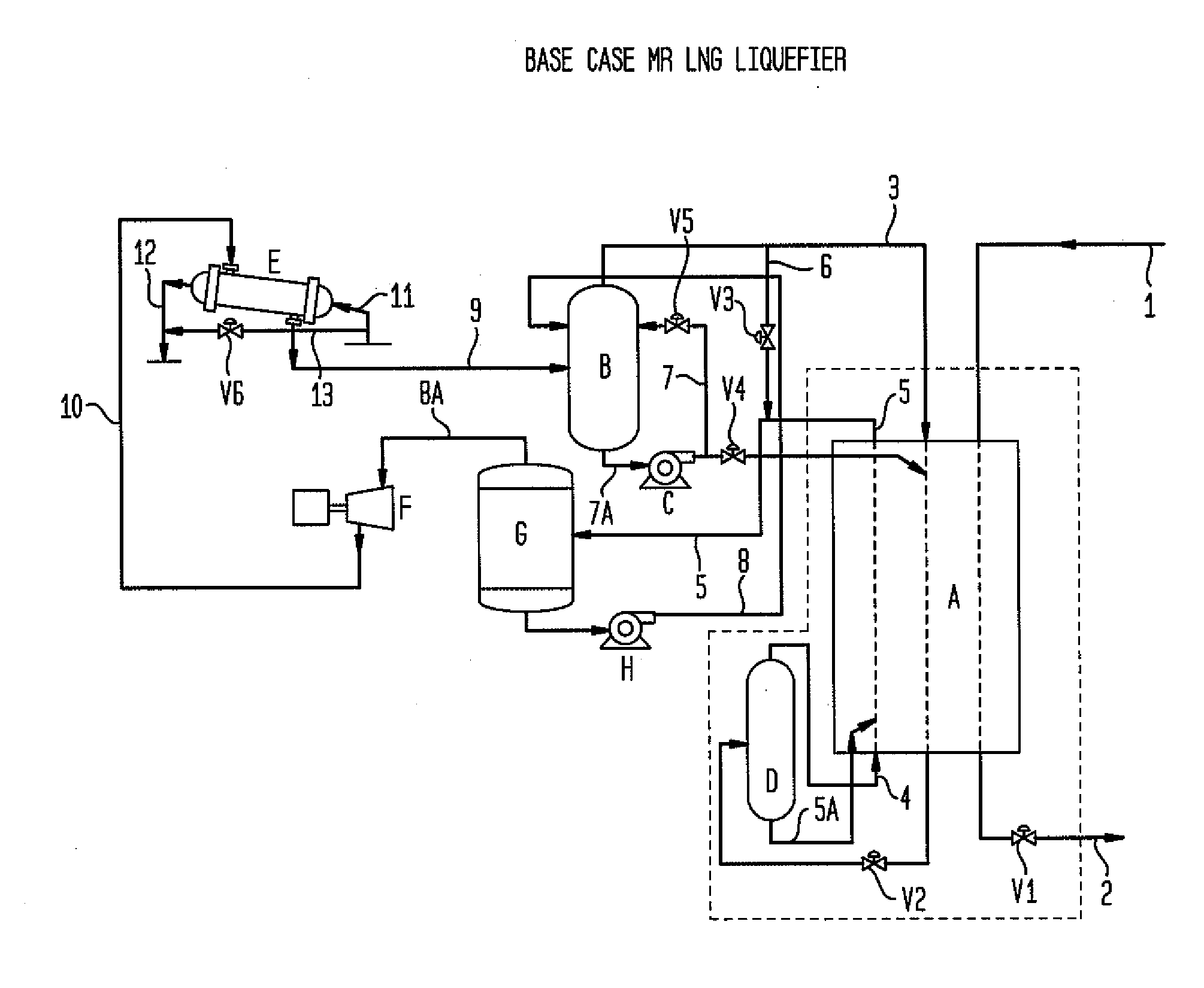
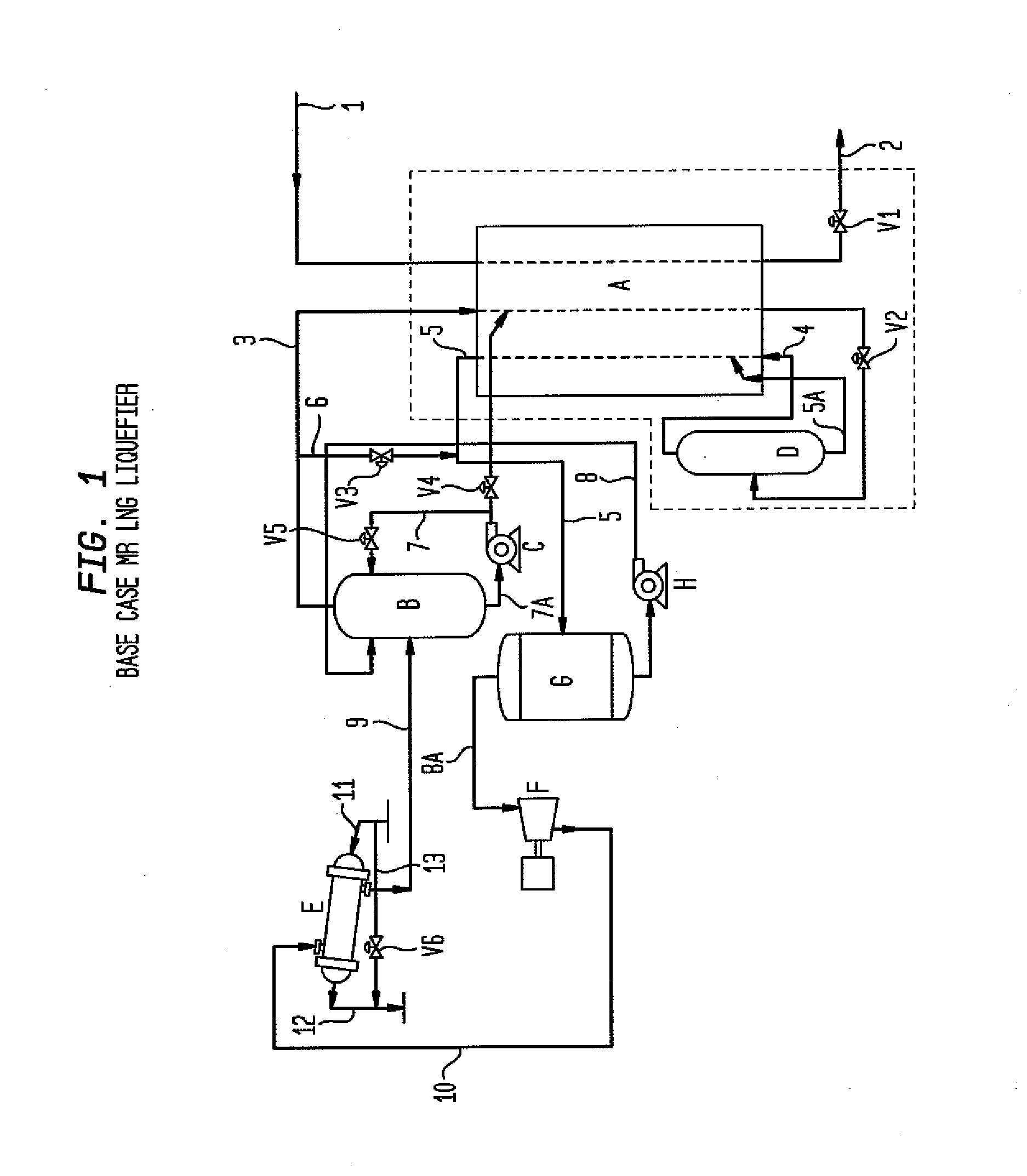
[0023]The gas is further purified in an adsorption system so that the carbon dioxide level is reduced below 50 ppmv and a large portion of the nitrogen is removed. Oxygen usually does not adsorb appreciably and about 50% of the oxygen is removed in each case. FIG. 1 illustrates a typical MR liquefier stream without process integration. In this case both storage tank losses and nitrogen rejection unit waste streams are not recovered.

[0024]Turning to the figures, FIG. 1, represents a base case mixed refrigerant liquefied natural gas liquefier. Purified natural gas is fed through line 1 through main heat exchanger A where it will be warmed and fed through v...


PUM


Abstract

A method for recovering liquefied natural gas from a gas mixture containing natural gas and impurities by subjecting the natural gas to a series of steps beginning with feeding a natural gas stream containing impurities to a nitrogen rejection unit; feeding the purified natural gas stream to a liquefier heat exchanger; expanding the liquefied natural gas and feeding the expanded liquefied natural gas to a flash vessel; flashing the liquid natural gas and separating the liquefied natural gas from the flash gas; and feeding the liquefied natural gas to storage and the flash gas to the nitrogen rejection unit.

Description

CROSS REFERENCE TO RELATED APPLICATIONS[0001]This application claims priority from U.S. provisional patent application Ser. No. 61 / 317,466, filed Mar. 25, 2010.BACKGROUND OF THE INVENTION[0002]The invention relates to the integration of a liquefied natural gas (LNG) liquefier system with a nitrogen rejection unit (NRU) so as to minimize the capital and operating costs while maintaining liquefied natural gas product purity requirements.[0003]Renewable methane can be recovered from a number of sources, such as anaerobic digestion of municipal or industrial waste streams, the degradation of biomass in landfills, the gasification of waste and biomass streams, amongst others. In many instances, this renewable methane require purification before it can be used and / or sold into higher valued markets, such as injection into the pipeline grid, as a feedstock for liquefied natural gas, as a vehicle fuel, or as a feedstock for the production of hydrogen. Further, the energy that is required to...

Claims


Application Information

Patent Timeline
Patent Type & Authority Applications(United States)
IPC IPC(8): F25J1/00
CPCC10L3/105F25J2290/62F25J1/0022F25J1/004F25J1/0055F25J1/0219F25J1/0258F25J1/0259F25J1/0262F25J1/0264F25J1/0291F25J2205/60F25J2210/06F25J2210/66F25J2220/62F25J2230/30F25J2245/02F25J2245/90F25J2290/32Y02E50/346F25J1/0279Y02E50/30
Inventor SETHNA, RUSTAM H.PAGES, GUILLAUME
Owner LINDE AG
Why Eureka
Try Eureka