
Oscillator

a quartz crystal resonator and oscillator technology, applied in the field of oscillators, can solve the problems of difficult low-cost manufacturing, distorted waveform of the sine wave output of the quartz crystal resonator, complicated structure, etc., and achieve the effect of reducing phase noise, reducing distortion of waveform, and not reducing phase nois

Inactive Publication Date: 2012-04-05
NIHON DEMPA KOGYO CO LTD
View PDF14 Cites 6 Cited by
  • Summary
  • Abstract
  • Description
  • Claims
  • Application Information

AI Technical Summary

Benefits of technology

[0010]The present invention was made under the above circumstances, and has an object to provide an oscillator capable of reducing phase noise.
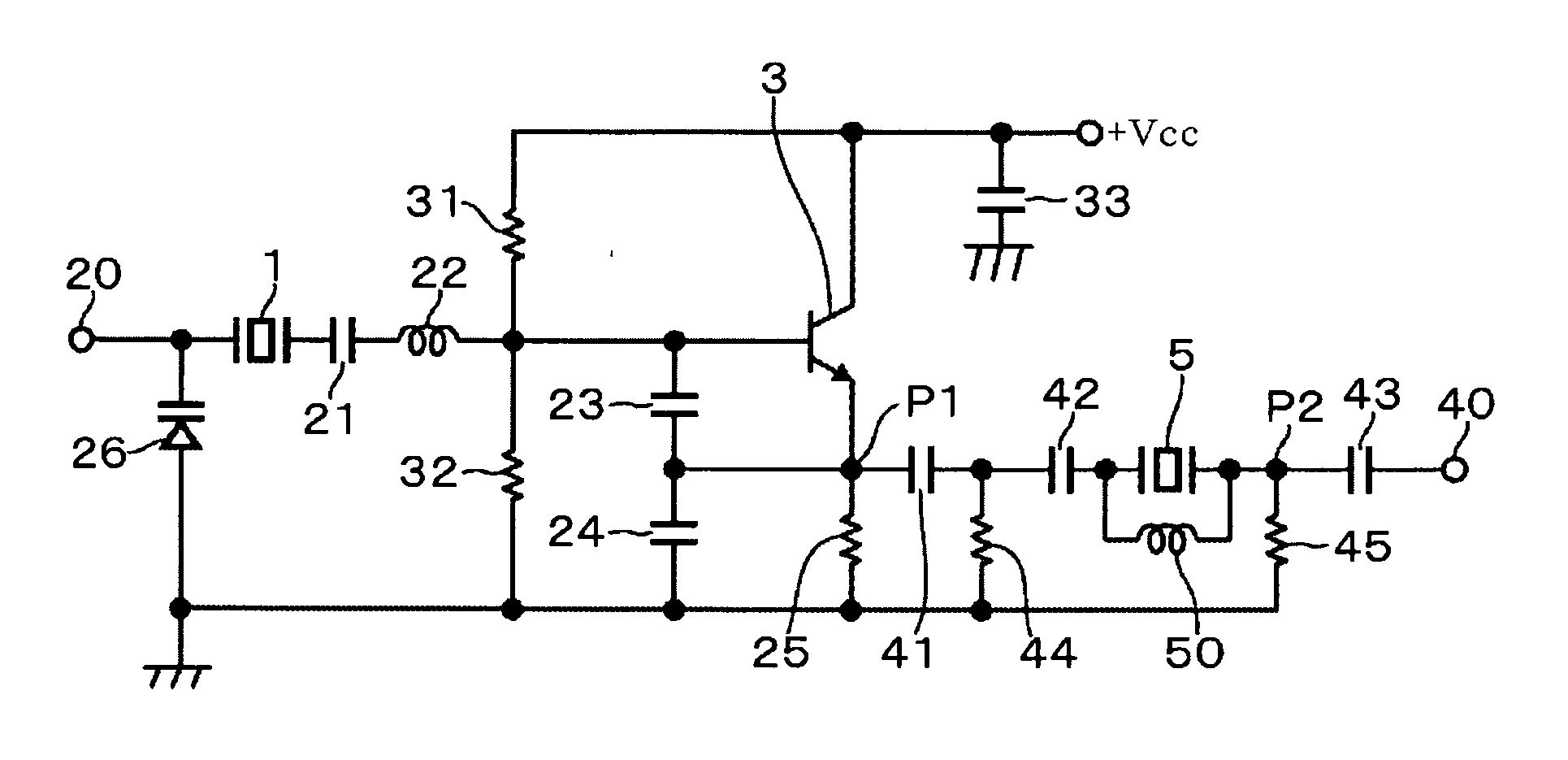
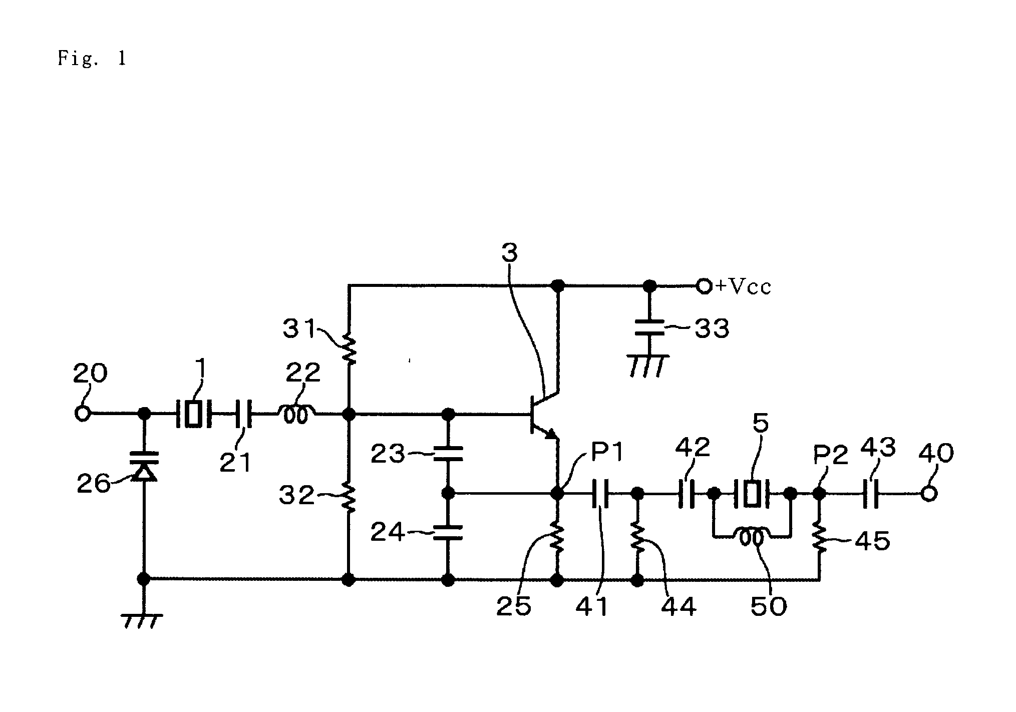
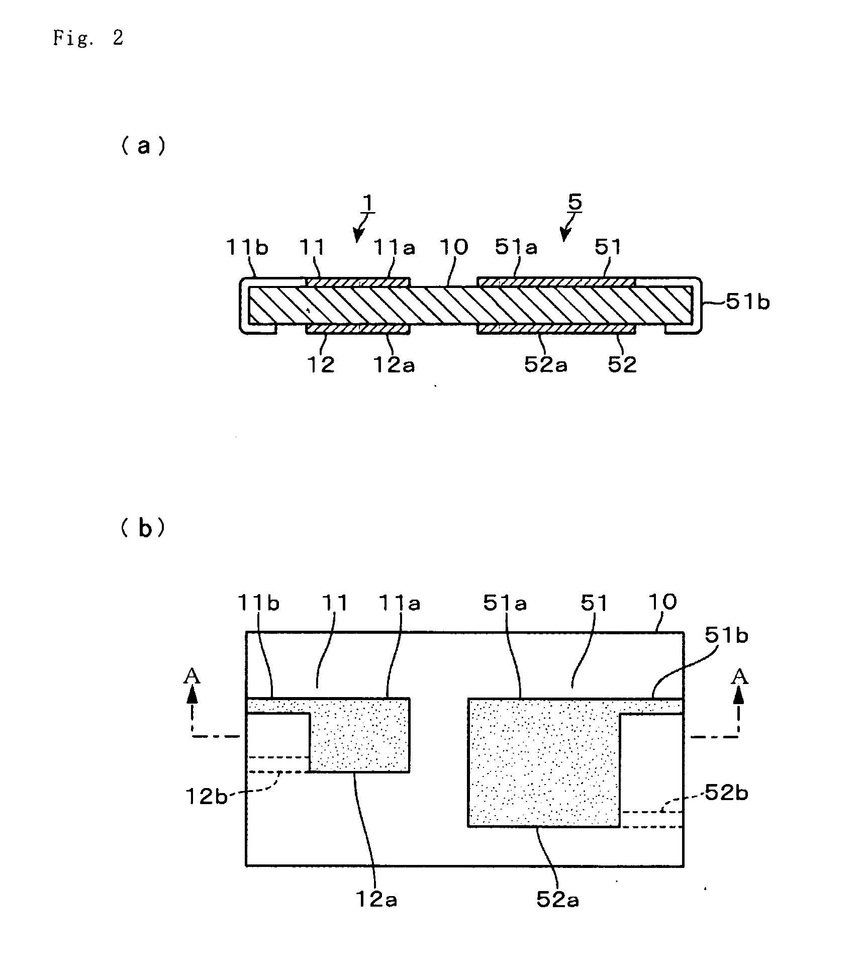
[0019]According to the present invention, since, in the oscillator including the oscillating part including the quartz-crystal resonator, the quartz-crystal resonator for waveform shaping to shape the frequency signal to the sine wave is provided inside or outside the oscillation loop, the distortion of the waveform is reduced, which enables a reduction in phase noise. The electrodes of the quartz-crystal resonator for oscillation and the electrodes of the quartz-crystal resonator for waveform shaping are provided on the common quartz-crystal piece and the quartz-crystal resonators are both placed in the same environment, and hence when the temperature changes, oscillation frequencies of the both quartz-crystal resonators change to the same degree. Therefore, even if the temperature changes, an effect of reducing phase noise is not impaired. Further, since the inductor causing the parallel resonance at the intended output frequency with the parallel capacitance of the quartz-crystal resonator for waveform shaping is provided, the frequency signal mainly passes through a mechanically oscillating portion in the quartz-crystal resonator, so that a noise component included in the intended frequency signal, for example, a fundamental wave, is removed. Therefore, the phase noise can be further reduced.
[0020]According to the other aspect of the invention, since, in the oscillator including the oscillating part including the elastic wave resonator, the elastic wave resonator for waveform shaping to shape the frequency signal to the sine wave is provided inside or outside the oscillation loop, the distortion of the waveform is reduced, which makes it possible to reduce phase noise.
[0021]The electrodes of the elastic wave resonator for oscillation and the elastic wave resonator for waveform shaping are provided on the common piezoelectric piece and the both elastic wave resonators are placed in the same environment, and therefore, the effect of reducing the phase noise is not impaired as described above.

Problems solved by technology

However, the waveform of the sine wave output from the quartz-crystal resonator is distorted when the sine wave passes through a circuit part such as the amplifier.
Further, in an area where the detuning frequency is 1 kHz or lower, noise reduction is also required, and to realize this has been an issue to be attained.
However, the circuit in this method has a complicated structure and is difficult to manufacture at low cost, which makes it difficult to produce it on a commercial basis.
This technique, however, is to compensate a frequency-temperature characteristic and is not a technique relating to waveform shaping.
However, the latter quartz-crystal resonator is not for shaping the sine wave and does not sufficiently remove a noise component included in a frequency signal.

Method used


Image

  • Oscillator
  • Oscillator
  • Oscillator

Examples


first embodiment

[0033]FIG. 1 is a circuit diagram showing a first embodiment of an oscillator of the present invention. The circuit in FIG. 1 is configured as a Colpitts oscillator circuit, and 1 denotes a quartz-crystal resonator for oscillation. One end of the quartz-crystal resonator 1 is connected to a base of a NPN transistor 3, which is an amplifying part, via a capacitor 21 for frequency adjustment and an extension coil 22. The transistor 3 amplifies a frequency signal oscillated by the quartz-crystal resonator 1 to feed the resultant frequency signal back to the quartz-crystal resonator 1. Between the base of the transistor 3 and a ground, a series circuit of capacitors 23, 24 for voltage division is provided, and a midpoint of the capacitors 23, 24 is connected to an emitter of the transistor 3.

[0034]Further, a DC power supply part Vcc applies a DC voltage of +Vcc to a series circuit of bleeder resistors 31, 32, and the voltage at a midpoint of the bleeder resistors 31, 32 is supplied to t...

second embodiment

[0053]In a second embodiment of the present invention, an oscillator is formed by using a SAW (Surface Acoustic Wave) resonator being an elastic wave resonator for oscillation instead of the quartz-crystal resonator 1 for oscillation in the first embodiment and using a SAW resonator for waveform shaping instead of the quartz-crystal resonator 5 for waveform shaping in the first embodiment. The SAW resonator for oscillation and the SAW resonator for waveform shaping use a common piezoelectric piece, and are formed so that the SAW resonator for oscillation and the SAW resonator for waveform shaping exhibit the same frequency-temperature characteristic which represents a temperature-dependent frequency change.

[0054]In the example using the SAW resonators instead of the quartz-crystal resonators as well, the distortion of an output waveform is reduced, which makes it possible to obtain a sine wave with high purity. Further, since the SAW resonator for oscillation and the SAW resonator f...


PUM


Abstract

An oscillator outputs a sine wave with high purity capable of reducing phase noise. In a Colpitts oscillator circuit using a transistor as an amplifying part, a quartz-crystal resonator for waveform shaping is provided outside or inside an oscillation loop. A quartz-crystal resonator for oscillation and the quartz-crystal resonator for waveform shaping are formed, with an electrode pair and an electrode pair being provided on a common quartz-crystal piece. A separation distance between the electrode of the quartz-crystal resonator and the electrode of the quartz-crystal resonator is set large so that they are not elastically coupled, or even when they are elastically coupled, their coupling degree is weak, and an inductor causing parallel resonance with a parallel capacitance of the quartz-crystal resonator is provided.

Description

BACKGROUND OF THE INVENTION[0001]1. Field of the Invention[0002]The present invention relates to an oscillator.[0003]2. Description of the Related Art[0004]A quartz-crystal oscillator oscillates by connecting an amplifier to a resonant circuit including a quartz-crystal resonator, and a voltage waveform corresponding to an oscillation waveform of the quartz-crystal resonator is a sine wave. However, the waveform of the sine wave output from the quartz-crystal resonator is distorted when the sine wave passes through a circuit part such as the amplifier.[0005]A demand for frequency stabilization of a signal represented by a signal of GPS is increasing year by year, and recent years have seen not a small demand that what is called a floor level at a 10 kHz detuning frequency or higher should be −160 dBc or lower in terms of SSB phase noise. Further, in an area where the detuning frequency is 1 kHz or lower, noise reduction is also required, and to realize this has been an issue to be a...

Claims


Application Information

Patent Timeline
IPC IPC(8): H03K3/36
CPCH03B2200/0008H03B5/326
Inventor KOYAMA, MITSUAKI
Owner NIHON DEMPA KOGYO CO LTD
Learn More